Testbeds
The CREW federation is built starting from existing testbeds at five different physical locations:
- A heterogeneous ISM test environment at iMinds incorporating IEEE 802.11, IEEE 802.15.1, IEEE 802.15.4, USRP software radios;
- A licensed cognitive radio testbed (including TV bands) at TCD that is based on the IRIS reconfigurable radio platform and the USRP;
- A wireless sensor network test environment at TUB incorporating Tmote Sky and eyesIFXv2 sensor nodes, Wi-Spy spectrum analyzers, USRP software radios and BEE2 FFGA platforms
- An LTE cellular test environment at TUD incorporating a complete LTE-equivalent base station infrastructure and SDR mobile user terminals.
- An outdoor heterogeneous ISM/TVWS at JSI.
In addition, advanced sensing platforms developed by imec and TCS will be integrated at several locations in the CREW federated platform, enabling high-sensitivity detection and identification of interferences.
CREW will physically and virtually federate components by linking together software and hardware entities from different partners using a standardized API, realizing advanced cognitive sensing functionality. In addition, the CREW federation will establish a benchmarking framework, enabling experiments under controlled and reproducible test conditions and providing methodologies for automated performance analysis, allowing a fair comparison between different cognitive concepts or between subsequent developments. Data sets created under benchmarked conditions according to a common data structure enable the emulation of CREW components in other experimental or simulation environments.
Explore the possibilities of the federated CREW testbed, or discover the different individual testbeds below. For in-depth information and access to the testbeds, please consult the CREW portal.
w-iLab.t (iMinds)
Important note: For a more detailed and up to date description of the w-iLab.t testbed, please consult the testbed documentation pages. A high-level overview of the testbed is given below.Context
Wireless testbeds enable to effectively test the wireless protocols or applications in a real-life environment. In such an environment, the spectrum is not 'clean', and the locations of the nodes are fairly random. Current testbeds generally offer very limited flexibility in terms of application scenarios, node failure and the like, and are therefore not the ideal validation tools for real-life wireless network operation. Further, one of the major research issues in wireless networks is the development of energy efficient protocols in order to enlarge the lifetime of the nodes and thus the network. However, in existing testbeds it is not possible to measure the energy consumption of each individual node efficiently.
Screencast showing the basic functionality of the w-iLab.t testbed. Best viewed in fullscreen HD.
w.iLab.t testbed
The w-iLab.t testbed includes both a wireless mesh and sensor network infrastructure. These networks can interact with each other, making it possible to test advanced scenarios such as using the mesh network as a backbone for the sensor network. Further, interference between both networks can be studied. In order to facilitate the emulation of realistic sensor scenarios and to measure the energy consumption, the testbed is equipped with a custom designed hardware solutions, called the Environment Emulator (EE). Using the EE, it is possible to emulate the behavior of any type of sensor or actuator without the need for real sensor/actuator hardware or the development of a full-blown sensor application. It is possible to emulate the battery depletion, depending on the real life power consumption of the sensor node. When the node's battery is depleted or the node is destroyed (e.g., in an explosion), the node can be switched off. The EE can be programmed to emulate a sensor event (e.g., temperature rise, motion detection), an actuator event or to support voice streams. Further, the EE can be used to monitor the energy consumption of each individual sensor. Altogether, this means that it is possible to assess the complete usability of a certain wireless sensor and actuator network application or protocol in a real-life environment. The initial core of w-iLab.t was based on the widely used MoteLab testbed from Harvard University.
The iMinds w-iLab.t has two setups the "w-iLab.t Office" and the "w-iLab.t Zwijnaarde" and it is part of the larger iLab.t facility. The "w-iLab.t Office" consists of a wireless Wi-Fi (IEEE 802.11a/b/g) and sensor network (IEEE 802.15.4) testbed infrastructure, deployed across three 90 m x 18 m floors of the iMinds office building in Ghent, Belgium. At 200 places throughout the office spaces, meeting rooms and corridors, wireless hardware is mounted to the ceiling.
The "w-iLab.t Zwijnaarde" is equipped with 60 wireless nodes: IEEE 802.11a/b/g/n, IEEE802.15.4, IEEE802.15.1 (Bluetooth) interfaces, software defined radio platforms (USRP) and spectrum scanning engines developed by imec. In addition, it offers mobile nodes to the experimenters. These mobile nodes feature the same equipment as the fixed ones, however they are mounted on Roomba vacuum cleaning robot. This facility is located in Zwijnaarde, Belgium, approximately 5 km away from the "w-iLab.t Office".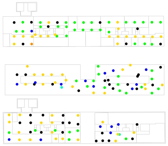
Node locations of the w-iLab.t testbed
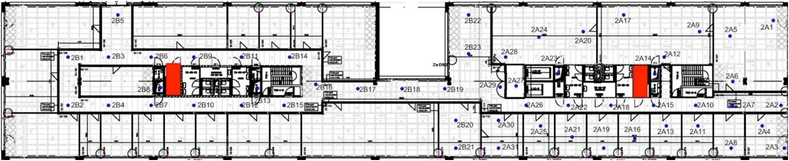
Map of the second floor.
Additionally, w-iLab.t is equipped with a shielded wireless environment. This environment is built up by 4 shielded boxes in which an iNode is installed. The iNodes are interconnected between the boxes by coax cables via a variable attenuator. By varying the signal attenuation, node mobility can be simulated in a repeatable way.
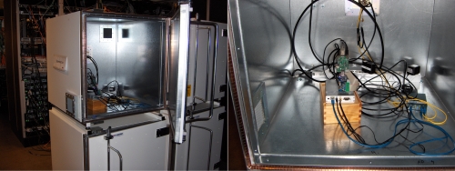
Left: RF shielded boxes. Right: iNode inside the box.
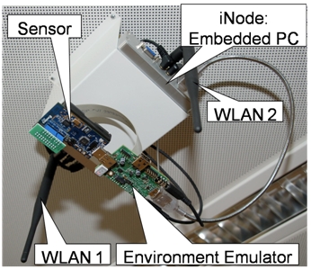
iNodes:
Every w-iLab.t node is generic and is equipped with one or more sensor nodes, an intermediate node with 2 WiFi 802.11 radios, the environment emulator and a Bluetooth interface.
The sensor nodes are Tmote Sky motes that use a Tiny OS development environment. They consist of a TI MSP430 processor running at 8MHz, 10KB of RAM, 1Mbit of Flash memory and an IEEE 802.15.4 compliant Chipcon CC2420 radio operating at 2.4GHz with a maximum indoor range of approximately 100 meters. Each node includes sensors for light, temperature, and humidity. The hardware setup is extendable with a large variety of other radios (e.g Software Defined Radio, sensing engine), as long as the radio has a USB or RS232 serial interface.
The intermediate nodes (called iNodes) are Alix 3C3 devices running Linux. These are mini PC's equipped with Ethernet, USB, serial, vga, audio and two IEEE 802.11 a/b/g interfaces. All the iNodes are connected to the management backbone using Power-over-Ethernet switches, making it possible to power up/down the iNodes as needed without physical interaction with the iNodes. The iNodes can become an active member of the experiment as it is possible to adjust the kernel, the driver, to add click router code or to add java-based applications.
Finally, the Environment Emulator is located in between the iNode and the sensor node.
iNode mounted to the ceiling.
Accessing the testbed
The w-iLab.t testbed is centrally managed for control and monitoring purposes. For getting started, request an account. Tutorials, documentation and other useful information is available here.
Contribution to CREW
The w-iLab.t testbed as well as new cognitive radio extensions will be made available in the federated testbed.
IRIS (CTVR, Trinity College Dublin)
Important note: For a more detailed and up to date description of Iris and the Iris testbed, please consult the CREW portal. A high-level overview of Iris and the testbed is given below.The reconfigurable radio consists of a general-purpose processor software radio engine, known as IRIS (Implementing Radio in Software) and a minimal hardware frontend. IRIS can be used to create software radios that are reconfigurable in real-time.
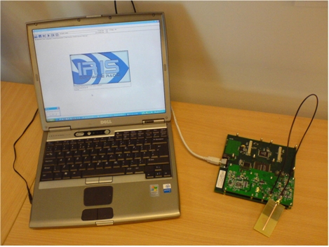 IRIS running on a laptop with the USRP frontend and a CTVR antenna
The fundamental unit for building reconfigurable radios in the IRIS Radio Architecture is the Radio Component (a unit of radio functionality). A user of IRIS creates a radio from an existing suite of Radio Components or by creating new components when necessary. These basic building blocks of the system are key to its ability to reconfigure. The Radio Components are designed to encapsulate radio functionality in a way that would facilitate their reuse among many applications and permit ultimate flexibility in the design of the overall system. In all there are six major entities:
1. Radio Component
A Radio Component is the basic unit of an IRIS implementation and comprises an individual stage in the signal-processing chain of an IRIS reconfigurable radio. The actual level of functional complexity that a Radio Component may encapsulate is at the discretion of the Radio Component designer. A wide range of components exist. Of interest to this project are components that are used for sensing, OFDM communication components, data logging components and other dynamic spectrum access related components.
2. XML Parser
Any give radio implementation is defined in an XML configuration file as a set of interconnected Radio Components. An XML parser is used to interpret the radio design specified in the XML configuration file and convert this information into a form that may be processed by the Component Manager and Radio Engine
3. Component Manager
The Component Manager loads the Radio Components specified in the XML configuration file and unloads a previously loaded radio configuration. The Component Manager also compiles an inventory of Components which may be located either on the host PC or from a remote location connected via Ethernet or internet, and these comprise the available Components that may be used as part of a radio implementation.
4. Radio Engine
The Radio Engine is the core of the IRIS framework. This implements the radio design to create an actual reconfigurable radio using the IRIS framework as the management and controlling entity. The Radio Engine relies on the Component Manager and control interface known as Control Logic.
5. Control Logic Manager
IRIS uses a Control Logic Manager (CLM) which is the main means of reconfiguring a radio configuration when the radio is in operation. This radio management feature can access the structure and parameters of all the Components and modify them as required. The CLM is independent of the Components (i.e. the CLM is a separate process that connects to the radio using a common interface and is fixed by any particular Component) and therefore may externally modify the operation and parameters of any of the Components that comprise the radio implementation.
6. IRIS API
The API used in IRIS is used to integrate an IRIS reconfigurable radio application into other applications. Specific functions that manipulate and control the IRIS Framework are abstracted from the core of the IRIS system enabling the sophisticated IRIS features to be accessed using a simple programming interface.
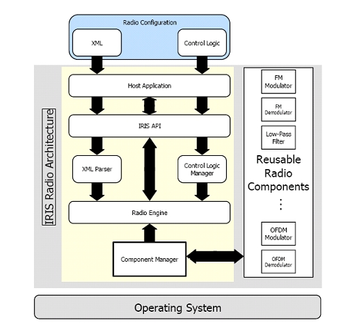 Overview of the IRIS system
Reconfigurability within IRIS
As stated above IRIS can be reconfigured in real-time. There are many definitions of reconfigurability so it is useful to explain in a little more detail as to what we mean. A software radio can be viewed as a number of signal processing stages that are linked together in a certain order to deliver the functionality required. With this in mind three levels of reconfiguration have been defined:
Level 1 - Parametric Reconfiguration involves the dynamic alteration of individual parameters of signal processing functionality. An example of parametric reconfiguration is a change in filter coefficients. An example specific to dynamic frequency management is the change of frequency setting in accordance with change of spectrum allocated to that particular radio.
Level 2- Structural Reconfiguration involves the alteration of the layout of the radio system or the replacement of some aspect of the software of the system while still performing the same overall application. For example structural reconfiguration occurs when the way in which a signal is processed is altered as in the case of the introduction of two stages of filtering instead of one. In this case the radio will still perform the same function but the reconfiguration may have the benefits of improving signal quality, power consumption or performance. An example specific to alternative frequency management regimes would be in the insertion of some new extra functionality within the existing software radio configuration, to make decisions about which frequencies the radio should use.
Level 3 - Application Reconfiguration involves completely replacing the software of the software radio with an entirely different software radio configuration. This type of reconfiguration allows a radio to completely change the application it performs. The same hardware being reconfigured from being a two-channel analogue FM transceiver to being a 10 channel digital BPSK transceiver is an example of application reconfiguration. Software download also falls into this category of reconfiguration. In terms of dynamic spectrum allocation it may be necessary for a radio to use an entirely different communication means to best take advantage of the new band of frequencies it has been allocated.
IRIS facilitates Parametric Reconfiguration, Structural Reconfiguration and Application Reconfiguration.
Hardware
IRIS interfaces with the USRP. It can in principle use any RF frontend. It simply needs a software component that can read from and write to that hardware (akin to a driver).
TWIST (TUB)
Important note: For a more detailed and up to date description of the TWIST testbed, please consult the CREW portal. A high-level overview of the testbed is given below.Context
Due to their distributed nature, the design, implementation and evaluation of sensor network applications, middleware and communication protocols is a difficult task. The first design steps can often be made with the help of simulations, however, they frequently force the designer to make artificial assumptions about traffic, failure patterns and topologies. The later steps of implementation and evaluation of application performance as well as assessment of error resilience and other nonfunctional properties, require the use of real hardware, realistic environments and realistic experimental setups. Real experiments with distributed systems like sensor networks quickly become very cumbersome as soon as the number of nodes exceeds a few dozens. A testbed allows to create, modify and observe the target configuration (both hardware and software) in its whole complexity including nodes, communication protocols, middleware and application. TWIST is a scalable and flexible testbed architecture for experimenting with wireless sensor network applications in an indoor setting.
TWIST Testbed at TUBerlin
The TKN Wireless Indoor Sensor Network Testbed (TWIST) is a multiplatform, hierarchical testbed architecture developed at the Technische Universität Berlin [1]. The selfconfiguration capability, the use of hardware with standardized interfaces and opensource software makes the TWIST architecture scalable, affordable, and easily replicable. The TWIST instance at the TKN office building is one of the largest remotely accessible testbeds with 204 SUT (system under test) sockets, currently populated with 102 eyesIFX and 102 Tmote Sky nodes. The nodes are deployed in a 3D grid spanning 3 floors of an office building at the TUB campus, resulting in more than 1500 m2 of instrumented office space. In small rooms (~14 m²), two nodes of each platform are deployed, while the larger ones (~28 m²) have four nodes. This setup results in a fairly regular grid deployment pattern with intra node distance of 3m. Within the rooms the sensor nodes are attached to the ceiling.
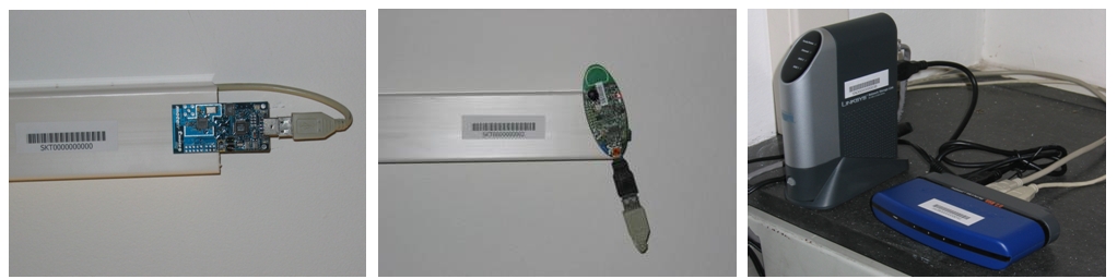 From left to right: Tmote Sky, eyesIFXv2, NLSU2 super node/USB hub
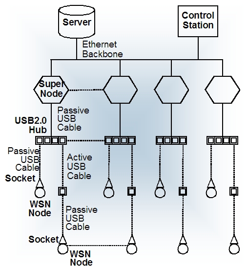 Schematic overview of the main TWIST hardware components
The primary user interface is webbased and provides support for registration, configuration and monitoring of test jobs. The testbed resources can be shared among multiple users as long as each accesses different SUT platform. The webinterface is coupled to a background testbed server that uses a RPC architecture to distribute the testbed management tasks to the supernodes, where they are executed in parallel on the attached SUT nodes. TWIST provides automatic trace collection and centralized time stamping service, as well as raw access to the serial I/O of the SUT nodes. The webinterface is accessible via http://www.twist.tu-berlin.de. A sample hardware instantiation of the TWIST architecture is depicted below.
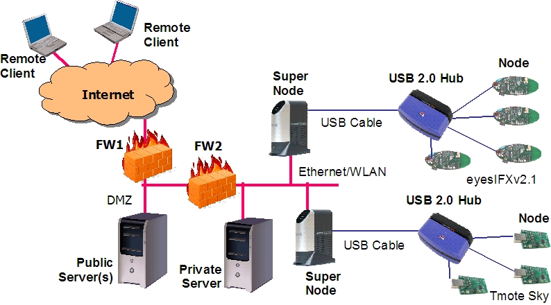 Hardware instantiation of the TWIST architecture
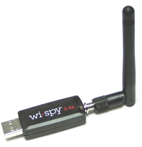 WiSpy USB dongle
The WiSpy devices can be used as basic sensing devices in a CR setup.
TWIST Contribution to CREW
The TWIST instance at TUB will be made available as part of the CREW federated testbed.
LTE/ LTE advanced testbed (TUD, Vodafone)
Important note: For a more detailed and up to date description of the LTE/LTE advanced testbed, please consult the CREW portal. A high-level overview of the testbed is given below.Context
The 3GPP LTE standard is stable now in its first release (Release 8), and the question is how good its performance is in real-world scenarios. LTE is also a good base for further innovations, but it must be proven that they offer performance advantages for the price of their complexity. A variety of advanced concepts such as cooperative MIMO are currently in discussion as future LTE extensions. Such novel schemes are researched within the EASY-C project via lab measurements and a multisite field test bed. The mobile Internet has finally arrived with the worldwide deployment of high-speed packet access (HSPA) networks and broad availability of third-generation (3G) terminals, mobile broadband USB sticks, and notebooks with integrated HSPA modules. With data flatrates, the usage of mobile Internet has skyrocketed in 2008. Third-generation technology was developed more than a decade ago, and the uptake after launch was below expectations in many cases. There are various reasons for that, including initial lack of handset availability and initial technology performance below predictions.
The Next Generation Mobile Networks (NGMN) Alliance has set out requirements for future mobile networks, and the Third Generation Partnership Program (3GPP) is addressing them with the development of long-term evolution (LTE). Among the requirements for LTE are increased average and peak data rates, reduced latency, spectrum flexibility addressing bandwidths of up to 20 MHz, and, last but not least, reduced cost of ownership. The performance of LTE meets the essential NGMN requirements, but not the preferred requirements in important key performance indicators (KPIs) like spectral efficiency and celledge throughput. Therefore, development of LTE technology is continuing beyond Release 8 to address operator requirements.
3GPP has initiated the “LTE-Advanced” study item and defined requirements. The research project Enablers for Ambient Services and Systems — Part C Wide Area Coverage (EASY-C) is developing technologies for future wireless systems such as LTE-Advanced. The special feature of EASY-C is that research ideas are tested in research field testbeds at the system level. In EASY-C, 16 partners work together across the value chain, including academic institutions, mobile operators, network infrastructure, antenna, and test equipment providers, terminal chipset vendors and semiconductor companies, and network planning specialists.
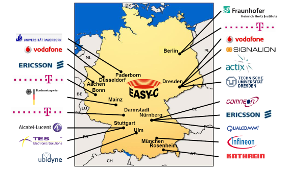 EASY-C Consortium
EASY-C Test Bed in Dresden
Two testbeds have been built and operated within the above mentioned research project EASY-C. One of them is the testbed in downtown Dresden Germany, using existing 2G/3G network sites of operators Vodafone and T-Mobile. Both operators are also involved in the trials. An additional testbed focused on applications enabled through LTE and advanced concepts is being set up in Berlin. The chosen testbed location in downtown Dresden covers various propagation conditions, which are of special interest for evaluation of fourth-generation (4G) systems with MIMO links and interference conditions typical in frequency reuse one networks like LTE, and for the development of advanced algorithms such as cooperative MIMO:
- A representative area of a medium-sized European city
- Hills in the south causing signal reflections
- A river through the city causing superrefractions and tropospheric refraction
- Urban areas with multistory buildings, leading to shadowing effects
- An average intersite distance of 500 m
In the first phase, one site with three cells started operating in April 2008. As shown in the picture below, this central site is located near Dresden’s main railway station.
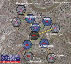 EASY-C cell structure downtown Dresden
EASYC - Contribution for CREW
The TUD contribution will be based on the EASY-C campus infrastructure, i.e, the EASY-C outdoor lab test bed which is directly operated by the Vodafone Chair research team. An LTE-like cellular infrastructure will be used where relevant network parameters are measured such as frame error rates, outage events, throughput or latency. One base station at rooftop level will be used which serves multiple UEs. This BS resides at the faculty of electrical engineering and information technology, TUD. Stationary and mobile user equipment will be used. Below are depicted, from left to right: mobile test UE, base station equipment, UE lab equipment.
 EASY-C test equipment.
External users of the TUD test bed will install their own equipment at the TUD test site. A predefined test setup is used which provides well defined and reproducible EASY-C LTE traffic – good for the CREW cognitive radio benchmarking initiative. The LTE network parameters are constantly monitored and recorded. The CR transceivers are then activated where the LTE performance parameters are compared for the non-CR and CR case. Hence, it will be possible to benchmark the impact of various CR schemes on a cellular infrastructure through a well defined set of reproducible test setups.
The Vodafone Chair as research facility will develop cognitive radio test cases as well. The envisaged algorithms will sense the quality of the analog transceiver frontends – an ambitious goal related to the well known Dirty-RF1 paradigm. Taking into account the transceivers quality, new and more precise cognitive radio decision making and resource allocation will become possible.
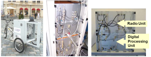
Outdoor heterogeneous ISM/TVWS VSN testbed
Outdoor heterogeneous ISM/TVWS testbed
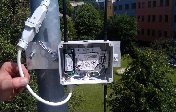
The Cognitive Radio part of the LOG-a-TEC testbed consists of several clusters of permanently mounted VESNA sensor nodes that are dedicated to experimentation with spectrum sensing and radio communications within wireless sensor networks. Each sensor node in these clusters is equipped with multiple reconfigurable radio interfaces that can be used in various modes. A license from the local regulator allows for experimentation in TV whitespaces as well as frequency bands for unlicensed devices.
Testbed is remotely accessible over the Internet and uses a dedicated, wireless management network to control individual sensor nodes in a cluster. Different approaches can be used to perform experiments, depending on the latency requirements and complexity of experimental scenarios: from high-level control using Python or graphical network stack composition to reprogramming the nodes with native applications. Radio propagation modeling tools can be used as well to plan the experiments.
In addition to permanently mounted nodes, several kinds of mobile nodes or instruments can be added to the testbed in special cases and after previous agreement.
Hardware
VESNA sensor node core (SNC) provides processing and storage at each sensor node. It contains an ARM Cortex M3 CPU at 64 MHz, 512 kB FlashROM, 64 kB RAM and an 2 GB SD card for code and data storage.
Different sensor node clusters contain different combinations of the following embedded radio hardware:
- CC2500-based reconfigurable transceiver for the 2.4 GHz ISM band. Packet-based and continuous transmissions at up to 800 kHz bandwidth, 500 kbps and 0 dBm transmit power. Energy detection using RSSI with 5 ms per channel sampling.
- CC1101-based reconfigurable transceiver for the upper UHF broadcast channels and 868 MHz European SRD band. Packet-based and continuous transmissions, including limited emulation of analogue transmissions, at up to 800 kHz bandwidth, 600 kbps and 12 dBm transmit power. Energy detection using RSSI with 5 ms per channel sampling.
- SNE-ISMTV-UHF, a custom-designed energy detector for the UHF broadcast band from 470 MHz to 862 MHz. Channel bandwidth from 1.7 MHz to 8 MHz, 0.032 dB resolution, 50 ms per channel sampling.
- SNE-ESHTER, a custom-designed spectrum sensing receiver for the UHF broadcast band from 470 MHz to 862 MHz. Off-line software processing of baseband samples up to 2 Msample/s, 25 kSample sample buffer depth. Energy detection up to 8 MHz bandwidth.
- AT86RF212 and AT86RF231 transceivers, compatible with the IEEE 802.15.4 standard in the 2.4 GHz and 868 MHz bands.
Additionally, a small number of software-defined radio nodes using the Ettus Reseach USRP N200 can be used in the test bed as needed. A Rohde & Schwarz SMBV100A vector signal generator and a FSV signal analyzer are available for on-site measurements.
See hardware page for more details on testbed hardware.
Locations
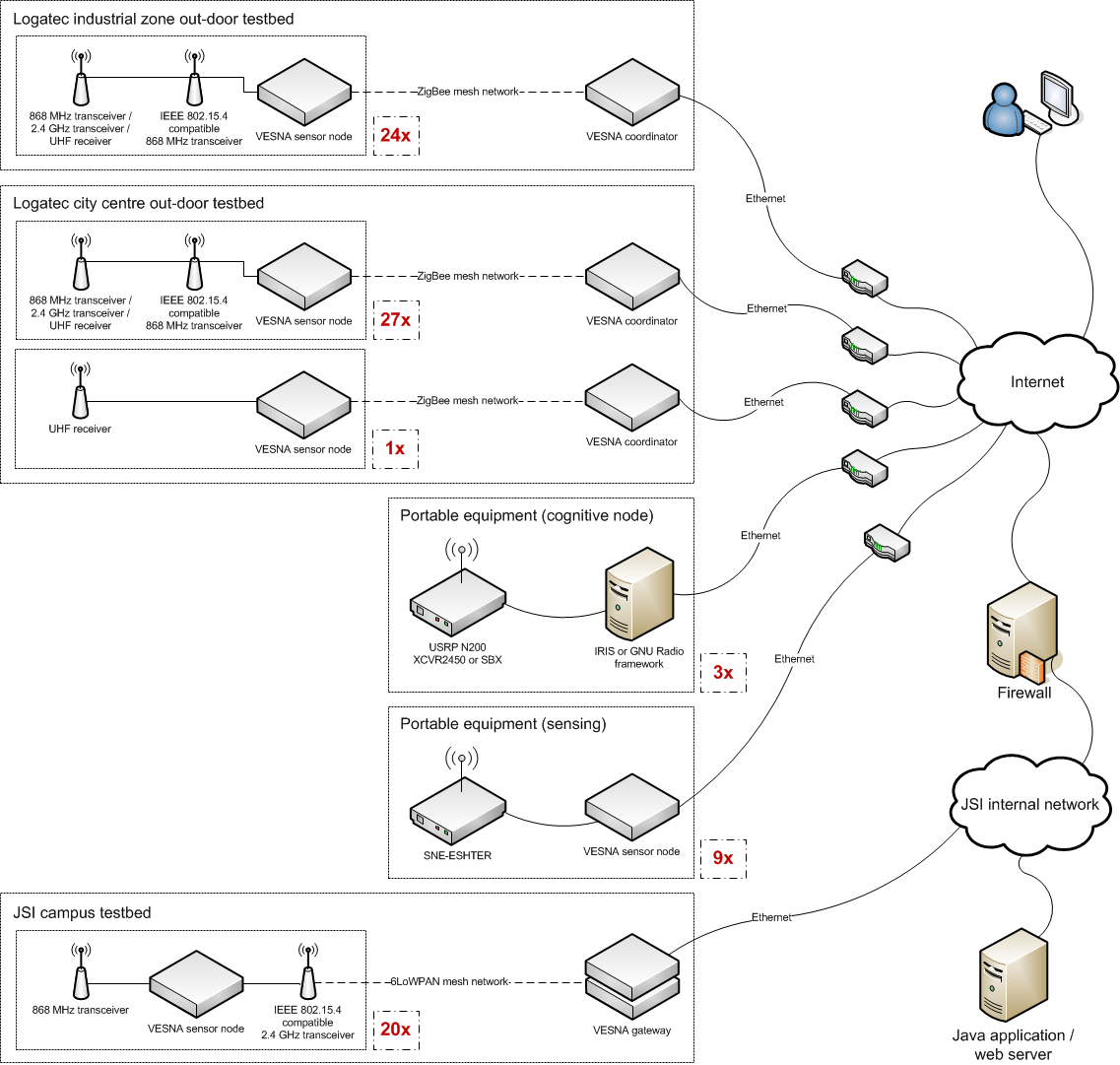
Cognitive Radio part of LOG-a-TEC testbed consists of the following permanently mounted clusters:
Logatec city
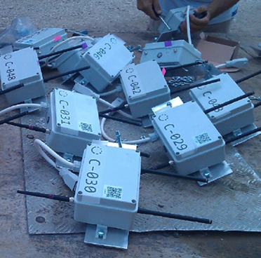
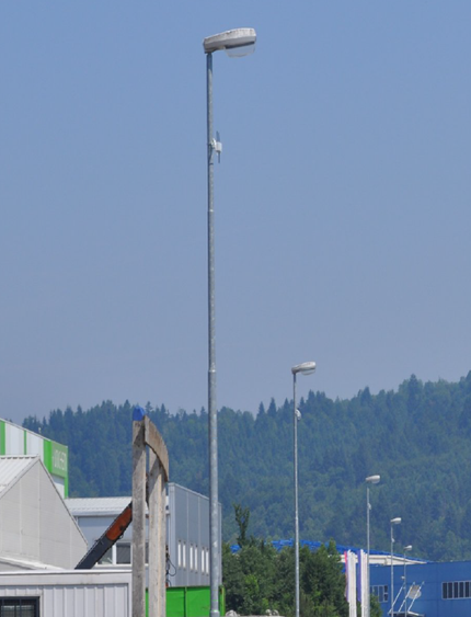
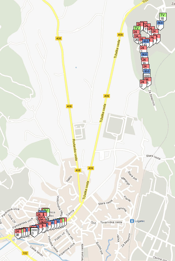
Logatec is a small city with approximately 10.000 inhabitants in the south-west of Slovenia. Three sensor node clusters cover approximately 350.000 m2 of out-door public space in the city center and an industrial zone using a total of 52 sensor nodes on street lights and other public infrastructure:
- Logatec industrial zone, street level cluster (24 nodes)
- Logatec city centre, street level cluster (27 nodes)
- Logatec city centre, antenna tower sensor (1 node)
These clusters are currently used for spectrum sensing experiments and radio environment mapping. Three distinct hardware node configurations are deployed:
- nodes with CC1101 and AT86RF212 radios (transmission and sensing in UHF and 868 MHz band, blue on map),
- nodes with CC2500 and AT86RF212 radios (transmission and sensing in 2.4 GHz band, red on map) and
- nodes with SNE-ISMTV-UHF and AT86RF212 radios (sensing in UHF band, green on map).
Nodes in the cluster are running the vesna-drivers firmware and use a dedicated, low-speed IEEE 802.15.4 management network (independent of the experimental radio hardware) for control and reprogramming. Each node is accessible from the Internet using a REST API and an application protocol similar to HTTP (ALH).

JSI campus
20 sensor nodes are mounted at the campus of the JoÅŸef Stefan Institute in Ljubljana, Slovenia. They cover approximately 3000 m2 of in-door and out-door space.
This cluster is currently used for experiments with packet-based transmissions and dynamic network stack composition in wireless sensor networks. All nodes in the cluster contain one CC1101 and one AT86RF231 radio.
Nodes at JSI campus are running Contiki operating system with a dual, composable networking stack. A 6LoWPAN network using the AT86RF231 radio is used to control and reprogram the nodes. Each node is directly accessible from the Internet using IPv6.
Software
The following is a list of the major software components of the LOG-a-TEC testbed.
Node firmware
- vesna-drivers is a custom developed C library for developing node firmware images. It supports experiment control and data retrieval over an application protocol similar to HTTP (ALH). Typical application developed with vesna-drivers supports signal generation and energy detection.
- Contiki OS is an open source embedded operating system with cooperative multi-tasking. In LOG-a-TEC testbeds it has been extended to support two networking stacks in parallel and a composeable RIME stack. It is typically used for experimentation with packet-based transmissions in wireless sensor networks.
- vesna-spectrum-sensor is an open source spectrum sensing application for spectrum sensing using VESNA sensor nodes. It is typically used when measurements with a mobile sensor node are performed in the testbed. It uses a wired RS-232 connection with a PC to report measurements.
Experiment support
- A LOG-a-TEC web portal provides an overview the testbed, its current state and allows for manual interaction with sensor nodes using a REST API requests. It also provides a graphical interface to the radio planning tools.
- vesna-alh-tools is a library and a collection of tools that allow for interaction with the testbed and experiment control from the Python language. vesna-alh-js is a similar, although less developed library, using Javascript.
- ProtoStack is a graphical tool for network stack development. It can be used to experiment with dynamic composition of communication services in the Contiki OS.
- GRASS-RaPlaT is an open-source radio planning tool. It contains a number of channel models that can be used to calculate radio coverage of a single node or a whole network. Integration with the LOG-a-TEC testbed provides raster maps of the area surrounding the testbed and can be used, for example, to predict received signal strengths for radio links in an experiment.
See software page for more details on testbed software.
| Attachment | Size |
|---|---|
| vesnaHardwareOverview Y4.png | 139.99 KB |
| boxes.png | 360.88 KB |
| poles.png | 309.46 KB |
| Logatec-clusters.png | 102.04 KB |
| UHFpole.png | 529.47 KB |