Hardware
In this section you can find detailed description of the hardware used in the testbed.
Configuration
Dresden’s LTE/LTE+ like testbed was set up in 2008 as part of the Easy-C project (www.easy-c.com).
The signal processing hardware includes:
- Sorbas602 eNodeB Simulators with ZF Interface to a Sorbas Radio Unit ("ZF Interconnect”)
- Sorbas202 Test UEs with ZF Interface to a Sorbas Radio Unit ("ZF Interconnect”)
- Sorbas472 Radio Units, by Signalion: EUTRAN band VII (2.5 - 2.57 GHz and 2.62 - 2.69 GHz) as well as close to band I (1.98-2 GHz and 2.17-2.19 GHz), 20MHz bandwidth, Tx power approx. 15dBm (indoor) and approx. 30dBm (outdoor), supports up to two Tx and two Rx channels.
They were supplied by Signalion (www.signalion.com). The eNBs and UEs are connected through IF interconnects at 70MHz with the radio unit frontend. The hardware supports up to two Tx and two Rx channels for MIMO capability. The testbed operates in EUTRAN band VII (DL @ 2670-2690 MHz / UL @ 2550-2570 MHz) with fixed bandwidth of 20MHz and in FDD mode.
The LTE testbed at TUD has been upgraded with a new spectrum license in the 2.1 GHz band (1980 MHz to 2000 MHz and 2170 MHz to 2190 MHz). This step was necessary to ensure the continuous operation of the LTE testbed when the spectrum license for 2.6 GHz is withdrawn due to commercial use of the corresponding frequencies in Germany. Along with the license, several nodes have been equipped with 2.1 GHz frontends. Note that only the RF parts have been replaced, while LTE eNB and UE baseband processing remains unaffected due to the modular structure of the equipment. Further note that as long as the 2.6 GHz license is not withdrawn, those frequencies are still available for experimentation.
The operation of the new equipment has been successfully tested. The internal US5 experiment “LTE Multi-Antenna Sensing” has been conducted in the 2.1 GHz frequency range.
Base station (eNB) and mobile terminal (UE) nodes each are connected to a host PC and configured with text files in XML format. The host computer also manages measurements of the received signals and stores them in dumps. At the eNBs, a GPS unit is used for synchronization, while the UEs employ GPS for position tracking. Additionally, UEs can be powered by a mobile power supply if necessary.
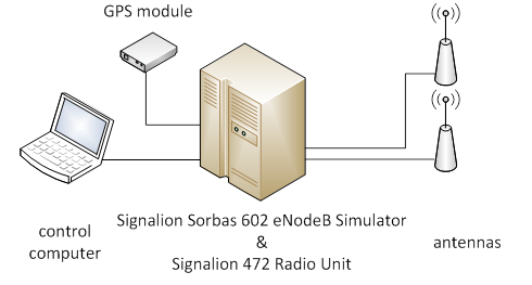
Configuration of a baste station node (eNB)
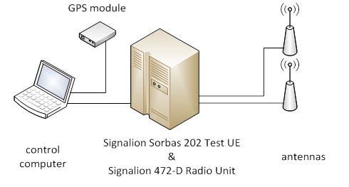
Configuration of a mobile terminal node (UE)
All UEs in the testbed, as well as the indoor eNBs are equipped with Kathrein 800 10431 omnidirectional antennas. The antennas of the outdoor eNBs are sectorized and of type Kathrein 800 10551. You can find detailed information about these antennas here:
http://www.kathrein-scala.com/catalog/80010431.pdf
http://www.kathrein.de/en/mcs/catalogues/download/99811214.pdf
Other testbed equipment includes six batteries that can power an individual UE for around 2-4 hours, GPS receivers for time synchronization, various cables, attenuators and splitters. Measurement equipment includes spectrum analyzers Rohde & Schwarz FSH4, Rohde & Schwarz FSQ8 and Rohde & Schwarz TSMW. For more details click on following links:
R&S FSH4 data sheet:
http://www.test-italy.com/occasioni/2013/rs_fsh8-18/FSH_dat-sw_en.pdf
R&S FSQ8 data sheet:
R&S TSMW operating manual:
http://www.rohde-schwarz.de/file_9446/TSMW_Operating_Manual.pdf
R&S TSMW software manual:
http://www.rohde-schwarz.de/file_11255/TSMW_Interface_and_Programming_Manual.pdf
| Attachment | Size |
|---|---|
| ltep05.png | 29.64 KB |
| ltep06.png | 28.13 KB |
Indoor and outdoor setups
For the CREW project, two experimentation setups are available.
The indoor lab features 5 eNBs and 4 UEs. While the hardware itself is stationary, the Tx and Rx antennas can be positioned anywhere in the lab room. Further, four additional UEs are mounted on studio racks/carts and can be moved within the building. The approximate transmit power is 15 dBm.
The outdoor lab consists of two base station sectors that are fixed on two opposing corners of the faculty building, approximately 150 m apart. In addition to the mobile indoor UEs from setup 1, three rickshaw UEs are available for outdoor experiments in the vicinity of the building. There are also 6 batteries which can supply an UE for around 2-4 hours. The transmit power is approximately 30 dBm.
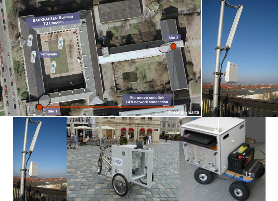
Outdoor setup
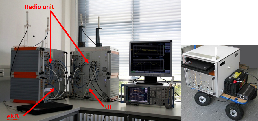
Indoor setup
| Attachment | Size |
|---|---|
| ltep07.png | 918.06 KB |
| ltep08.png | 494.97 KB |
Secondary System
The Signalion Hardware-in-the-Loop (HaLo) is a platform designated to simplifying the transition from simulation to implementation. To support cognitive radio setups that consider a primary/secondary user configuration, the LTE testbed has been extended by a HaLo node that can take the role of the secondary user. On the HaLo device, a novel modulation scheme called Generalized Frequency Division Multiplexing (GFDM) is now available.
This enables experimenters to consider experiment setups in LTE testbed, where the LTE system can act as a monitored primary system, while the GFDM system can run as an interfering secondary system.
HaLo Concept
The HaLo consists of a wireless transceiver that can operate in the 2.6 GHz frequency band. The concept is such, that complex valued data samples are transmitted to the device’s memory via USB from a control computer. The samples can be either read from a previously recorded file or generated on the fly e.g. by a Matlab script. The signal is transmitted over the air and received in a similar way. The device digitizes the signal and stores complex valued samples to an internal memory before they are fed back via USB to the control computer.
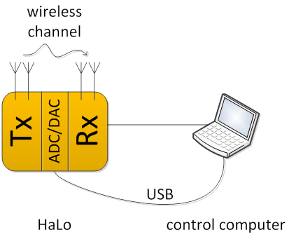
The HaLo setup
Note that due to limitations in the HaLo’s internal memory real-time operation is not possible.
GFDM Theory
The transmission scheme chosen to be implemented on the HaLo device to act as a secondary system in the testbed is a novel, non-orthogonal and flexible modulation scheme called GFDM. The concept is such that a multicarrier signal is transmitted, quite similar to the well know and established OFDM scheme, however one of the differences is in the pulse shaping of the individual subcarriers. This step allows shaping of transmissions and produces a signal with particularly low out-of-band radiation, which is a very desirable property in cognitive radio. For further details please refer to:
https://mns.ifn.et.tu-dresden.de/Lists/nPublications/Attachments/826/Michailov_N_VTCfall12.pdf
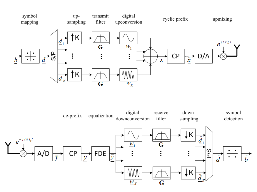
GFDM transmitter and receiver block diagram
| Attachment | Size |
|---|---|
| ltep09.png | 26.04 KB |
| ltep10.png | 51.37 KB |