IMEC sensing engine documentation
To achieve dynamic spectrum access, sensing techniques are crucial. The IMEC Sensing Engine can add sensing capabilities to radio systems and enable the evaluation of cognitive network solutions. Both hardware and firmware are reconfigurable, allowing to support and evaluate a wide range of sensing applications. A CREW application programming interface (API) is implemented as a Linux library, to ease the writing of new applications in a standard way. Currently, eight prototypes are deployed in the CREW w-iLab.t test-bed. These are connected by means of an USB interface to their corresponding Zotac nodes. Figure 1 shows an unpackaged version of the IMEC sensing engine with scaldio frontend.
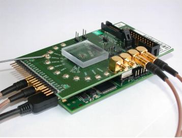
Figure 1. Unpackaged IMEC sensing engine with a Scaldio-2B wide band front-end.
At present seven units are deployed in the w-iLab.t Zwijnaarde testbed and one is deployed in the w-iLab.t office testbed. An introduction of how to access the IMEC sensing nodes in the CREW w-iLab.t facility is available on following pages:
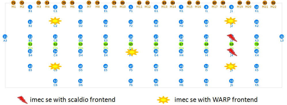
Figure 2. Deployment of IMEC sensing engine in the CREW Zwijnaarde w-iLab-t test-bed
The next sections focus on developing firmware for the IMEC sensing engine. Additional information can be found in following documents:
| Attachment | Size |
|---|---|
| SensingPrototypes-20110822.pdf | 880.07 KB |
| SensingEngine_UserManual_CREW.pdf | 1.43 MB |
| SensingEngineScaldio.JPG | 24.01 KB |
| 20140114_CREW_training_days_imecse_v1.0.pdf | 1.01 MB |
Hardware overview
Different hardware realizations of the IMEC sensing engines exist. This section details the used hardware for IMEC sensing engines, as deployed in the CREW w-iLab-t test-bed.
The IMEC sensing engine consists out of three main components: a digital processing part, an analog front end and an antenna. The following paragraphs detail these:
- The SPIDER digital board contains the IMEC DIFFS chip, which is the key component of the sensing real time signal processing (Figure 1.a). This board has two generations: version 1 and 2 respectively. All deployed prototypes for CREW use version 2. Each board has a SPIDER identification number bigger than 128. Specifically this number is derived by adding 128 to the number on the white label of the spider board. These SPIDER identification numbers are available in the test-bed documentation section, eg for the CREW Zwijnaarde w-Ilab-t test bed. An FPGA and on board SRAM allow to reconfigure the SPIDER board. Currently two configurations exist according to the connected front-end type.
- The analog front end board downconverts the signal band of interest to base-band. Two types of front-end are supported for the SPIDER v2 board (*):
- The IMEC Scaldio-2B wide band front-end, that supports sensing between 520MHz till 6.32 GHz (Figure 1.b). Note that an appropriate antenna is needed for the selected band.
- The commercial WARP frontend for the 2.4 GHz and 5.2 GHz ISM bands (Figure 1.c).
(*) The SPIDER board needs to be configured properly to support one of these front-end types.
- To enable correct sensing a suitable antenna is required. For the WARP front end a WiFi antenna is typically used (Figure 2.a). For the Scaldio-2B front end a suitable antenna for the frequency band of interest is recommended. Figure 2.b shows a wide band antenna suited for a frequency range between 800 MHz till 2.5 GHz.
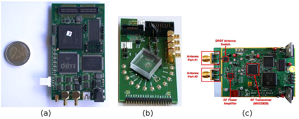
Figure 1 : Overview of boards for IMEC sensing engines deployted in CREW (a) SPIDER v2 digital board (b) Imec Scaldio-2B analog front-end (c) WARP analog front-end. A two Euro coin is shown to indicate the size of these boards.
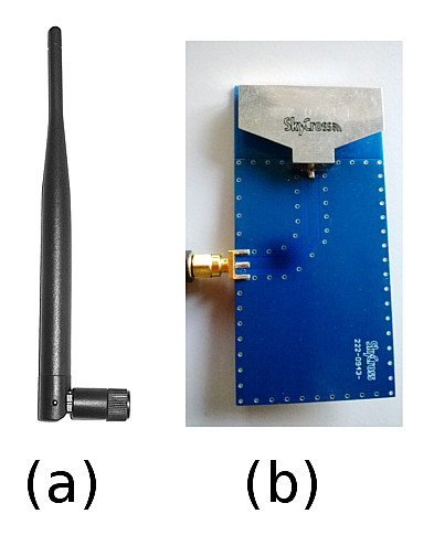
Figure 2 : example antenna's (a) Wifi antenna (b) broadband antenna for 800MHz .. 2.5 GHz range
| Attachment | Size |
|---|---|
| SPIDER-SCALDO2B-WARP.jpg | 112.92 KB |
| SE-antennas.jpg | 32.63 KB |
Software and hardware configuration
To use the IMEC sensing engine the hardware needs to be configured with the CREW API. The corresponding libraries are typically pre-compiled for the Zotac nodes of thw w-iLab.t test bed. Here we briefly illustrates the main configuration steps, as required when updating or extending nodes with Imec sensing capabilities. We show this for the default organisation of the development files, as illustrated in the user manual
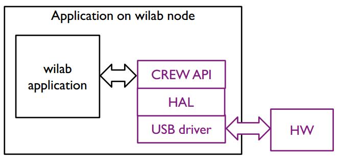
Figure 1 : software stack of the IMEC sensing engine
Software configuration
A high level overview of the software is shown in Figure 1. The software runs on Linux. The standard (lib)USB development kit implements the low level communication with the USB port on the SPIDER hardware board. An advantage of this approach is that the hardware abstraction layer (HAL), CREW sensing API (application programming interface) and application can be developed in user mode instead of kernel mode. The configuration is done as follows.
- Start up a terminal session
- Navigate to the top level directory of the development kit. You see two directories : "software" and "spider"
- cd spider/software/usb_interface/SensingEngine/ : this is the point where applications can be developed on top of the CREW sensing API
- source environment.csh : configure the environment with some additional variables
- pushd $USB_DIR : jump to directory with the spider HAL to communicate with the SPIDER board over USB
- make clean; make : build the spider API
- cd ../../platforms/swi/ : go to directory with the DIFFS HAL
- make clean ; make shared : build a shared library of the abstraction layer
- popd : jump back to the SensingEngine directory
- make clean ; make : build the CREW SensingEngine API
Hardware configuration
For CREW, the hardware configuration of the IMEC sensing engine is fixed. Two hardware configurations exist: one for systems equiped with a SCALDIO-2B front end, and another one when a WARP front-end board is present. In the spider/software/usb_interface/SensingEngine/ directory two scripts are available. Execute one of these to properly configure the SPIDER board:
- source environment.csh : only needed for a new terminal session
- ./setupscaldio.sh : execute this on nodes equiped with a Scaldio front end
- ./setupwarpfe.sh : execute this on nodes equiped with a WARP front end
With the command lsusb the hardware configuration can be checked. If the unitialised spider board is connected to the Zotac node, a USB device with ID 04b4:8613 of Cypress Semiconducor Corp. is present. After the hardware set-up this device is replaced by a USB device with ID 221a:0100. This signals that the SPIDER board is ready to use.
| Attachment | Size |
|---|---|
| SE-software-stack.JPG | 32.32 KB |
Program examples using the Imec sensing engine API
The Imec sensing engine is programmed in C, and can be set-up, configured and used with the sensing API. Using a simple example the use of this API is illustrated for the FFT_SWEEP mode. Both a single FFT sweep as multiple FFT sweeps are shown. This is illustrated for an Imec sensing engine equiped with a WARP front-end. A zip archive containing the source code of the examples is included below.
To conclude we provide an overview of the other modes as supported by the Imec sensing engine.
FFT_SWEEP example
The Imec sensing engine supports several modes: for this example uses FFT_SWEEP sensing scheme. This returns 128 points per selected channel. Figure 1 shows the output of one FFT sweep, for channel one to four for WARP, covering center frequencies 2412, 2432, 2452, 2472.
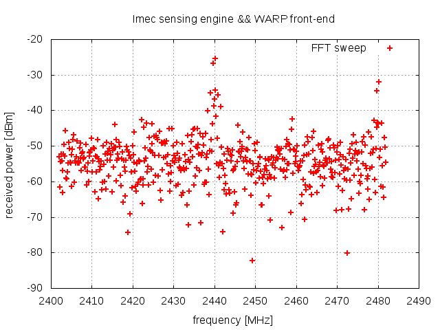
Figure 1 Output of one FFT sweep in the ISM band
The sensing engine is programmed in C. Items (1) .. (8) show the necessary steps to configure the sensing engine, and to produce the data shown in Figure 1. The full source code is available in the zip archive, specifically in the warp_single_FFT_SWEEP.c program file. In (9) we show how the program can be extended to do multiple sweeps.
The next paragraph discuss the required calls to the sensing API to produce the result.
Convention:
Type declarations are highlighted in green, and code snippets in blue. Calls to the sensing engine API are underlined.
1) Open the sensing engine handler
To open an Imec sensing engine board both the spider number and
front end number need to be used. The output is a software handler
that is used for the sensing engine API function calls.
se_t sensing_engine_handler;
sensing_engine_handler = se_open(spider, warp);
With:
- spider: an integer containing the spider board number. This number is bigger than 128 for spider v2 boards
- warp: a constant value 0 to select the WARP front end.
2) Initialize sensing engine
After checking the status of the sensing engine, the se_init function is
invoked to allocate memory and start adres for the my_se_config struct.
With this struct the parameters for the sensing engine will be configured.
A return value equal to 1 indicates that this step succeeded
int result = 0;
struct se_config_s my_se_config;
// configure WARP FFT sweep
Other sensing modes
- FFT_SWEEP : shown in example above. A 128 point FFT is performed for each configured channel.
- WLAN_G: determines the instantaneous power in each selected channel for IEEE802.11g spectrum.
- WLAN_A: similar as WLAN_G, for IEEE802.11a spectrum.
- BLUETOOTH: determines instantanious power for IEEE802.15.1 spectrum.
- ZIGBEE: similar to BLUETOOTH, for IEEE802.15.4 spectrum
- LTE: not implemented.
- DVB_T: detection of DVB_T signals. Only applicable for the Scaldio2B front-end.
- ISM_POWER_DETECT: determines instantaneous power in the 2.4 GHz ISM band, with a granularity of 1 MHz.
- TRANSMIT: not implemented.
- ADC_LOG1: logging of ADC values as retrieved from the front-end. Debug mode for sensing engine equiped with a Scaldio2B front-end.
- ADC_LOG2: logging of ADC values as retrieved from the front-end. Debug mode for sensing engine equiped with a WARP front-end.
- STANDBY: not implemented.
| Attachment | Size |
|---|---|
| WARPexample.zip | 5.62 KB |
| Imec-sensing-engine-WARP-single-FFT-sweep.png | 10.84 KB |
| Imec-sensing-engine-WARP-multiple-FFT-sweep.png | 324.93 KB |