Easy experiment configuration
Tool Location (OpenVPN required) http://ec.wilab2.ilabt.iminds.be/CREW_BM/BM_tools/exprDef.html
The experiment definition tool allows the experimenter to configure the system under test and the wireless background environment. Two types of configuration are possible. One can start from scratch and create a full experiment definition or configure from an existing one.
For the latter case, a number of solution under test and background environment configuration files are stored in CREW repository.
For detail explanation, refer the section CREW experiment definition.
Experiment Definition Tool
The experiment definition tool is used to define, configure, and make changes to wireless experiments that are to be conducted on different testbeds. Before explaining the experiment definition in detail, an experimenter need to be familiar with the concept of experiment resource grouping. This concept is taken from the cOntrol and Management Framework (OMF) developed by the collaborative effort of NICTA and Winlab [1].
The experiment resource grouping concept treats an experiment as a collection of resources aggregated into groups. Resources can be any of these but not limited to WI-FI nodes, sensor nodes, spectrum sensing devices, and software-defined radios. With in a group, multiple nodes run different applications that were predefined in an application pool. And a single application as well defines a number of optional measurement points. In figure 1, we show a simple experiment scenario where two WI-FI nodes (node 1 and node 3) sends TCP and UDP packets towards two receiver WI-FI nodes (node 1 and node 3). In real life this could mean, for example, Node1 performing a file transfer to Node2 while at the same time listening to a high quality (192kbps) radio channel from Node3 and Node2 is watching a 10Mpbs movie streamed from Node3.
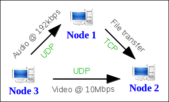
Figure 1. simple experiment scenario using three WI-FI nodes.
The experiment shown above, also called Iperf Sender Receiver (ISR) experiment , is realized using the iperf measurement tool which is a commonly used in network testing application. The iperf tool has a number of output formats instrumented for different uses. For example when iperf is used for TCP streaming, throughput information is displayed and when used for UDP streaming, jitter and packet loss information are displayed to the end user. Therefore an application can instrument more than one output to the user and in the context of OMF, they are refereed to as measurement points (MP). For this experiment scenario, transfer, jitter, and loss measurement points are used. A graphical view of experiment resource grouping is shown in figure 2.
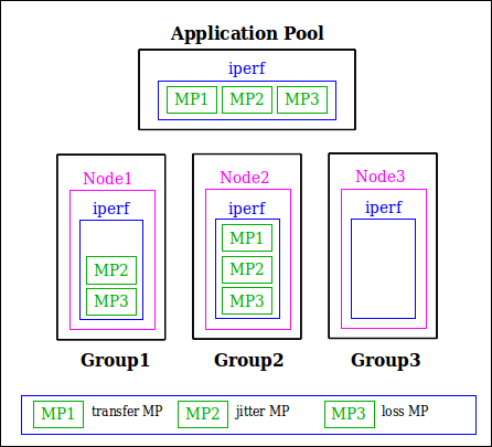
Figure 2. Experiment resource grouping of the experiment scenario. Note that Node3 does not have measurement points since it only streams UDP packets.
Next we look at how experiment is defined in the experiment definition tool. The ISR experiment, defined previously, is used here to illustrate tool's usage. From an experimenter point of view, there are two ways of defining an experiment. These are defining new experiment and defining from a saved configuration file.
Click the Start New Configuration link to start defining a new experiment. The first stage of experiment definition is experiment abstract. Here the experimenter can give a high level information about the experiment such as project name, experiment name, title, author, contact information, summary, and duration. Figure 3 shows the experiment abstract of the ISR experiment.
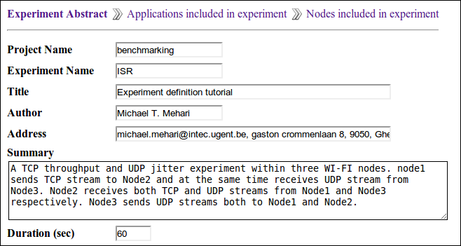
Figure 3. Experiment abstract definition of ISR experiment.
The next step is application definition. Here we create the application pool containing all applications that will be used in the experiment. Figure 4 shows the iperf application from ISR experiment application pool.
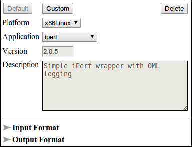
Figure 4. iperf application defined inside the application pool.
The last step in experiment definition tool is binding applications from the pool to different nodes of the wireless testbed. It involves platform specific node selection from testbed layout, interface configuration of group of nodes, and finally binding applications to nodes. Application binding involves a number of steps which are application selection, optional output instrumentation, input parameter configuration, and application timeline definition. Figure 5 shows the node configuration section (only shown for group Node1) of the ISR experiment.
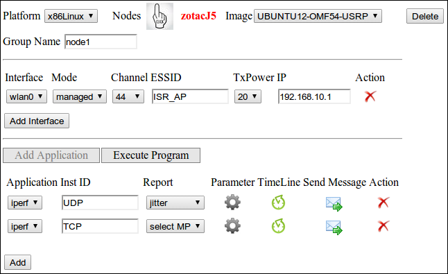
Figure 5. Experiment node configuration of ISR experiment.
Finally after finish configuring the experiment definition, we save it to a configuration package (name it ISR) composed of three files. These are XML configuration file (ISR.xml), OEDL (OMF Experiment Description Language) file (ISR.rb), and a network simulation file (ISR.ns) containing all configuration setting to be used inside emulab framework [2]. We explain the content of the XML configuration file in this section but the rest two files are explained on a separate page.
In CREW, XML is used as a configuration format for experiment descriptions and the XML configuration of the experiment definition in particular is a subset of the CREW common data format. An overview of the XML configuration of the ISR experiment is shown in figure 6.
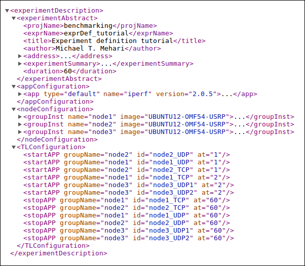
Figure 6. Excerpt from ISR experiment XML configuration file
Defining an experiment from a saved configuration file
For the experimenter, defining everything from scratch might be time consuming. An experimenter can use an existing configuration file or customize it according to his need. Reconfiguration is done first by downloading the configuration file (look CREW repository, background environments section in CREW portal) and then loading it on the "Load/Configure Experiment" section of the experiment definition tool. Finally, start reconfiguration and save it after finish modification.
[1]. Thierry Rakotoarivelo, Guillaume Jourjon, Maximilian Ott, and Ivan Seskar, ”OMF: A Control and Management Framework for Networking Testbeds.”