Introduction
In this section the basic information about the testbed is presented. The possibilities and limitations of the setup are also described.
Basic information
TUD coordinates the test activities that are related with the EASY-C testbed. Cellular use cases and CR-related field trials are provided by the Dresden test bed, which is supervised by TUD.
The TUD contribution is based on the EASY-C campus infrastructure, i.e, the EASY-C outdoor lab test bed which is directly operated by the Vodafone Chair research team. An LTE-like cellular infrastructure is used where relevant network parameters are measured such as frame error rates, outage events, throughput or latency. One base station at rooftop level will be used which serves multiple UEs. This BS resides at the faculty of electrical engineering and information technology, TUD. Stationary and mobile user equipment are used. Below are depicted, from left to right: mobile test UE, base station equipment, UE lab equipment.
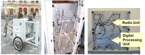
EASY-C test equipment.
External users of the TUD test bed need to install their own equipment at the TUD test site. A predefined test setup is used which provides well defined and reproducible EASY-C LTE traffic – good for the CREW cognitive radio benchmarking initiative. The LTE network parameters are constantly monitored and recorded. The CR transceivers are then activated where the LTE performance parameters are compared for the non-CR and CR case. Hence, it will be possible to benchmark the impact of various CR schemes on a cellular infrastructure through a well-defined set of reproducible test setups.
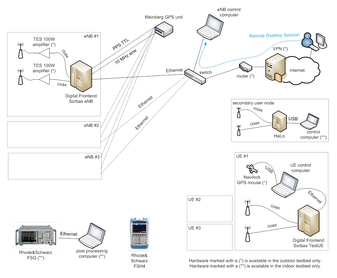
Another possibility for external users is to connect via Remote Desktop to the TUD indoor test bed to perform experiments with a fixed setup of one eNB, one UE, National Instruments USRP 2920 and one Signalion HaLo device.
Please click on the thumbnail below to get an overview picture of the hardware available in LTE advanced testbed.
| Attachment | Size |
|---|---|
| p01.png | 179.31 KB |
| ltep03.png | 14.91 KB |
Usage of the testbed
Two experimentation setups are available: the indoor lab and the outdoor lab.
In order to conduct experiments in the LTE+ testbed, participants are required to bring their spectrum sensing and/or secondary system hardware to Dresden, if the experiment cannot be performed by a USRP or HaLo device. In order to pre-evaluate certain theories and algorithms, a testbed reference signal in the form of baseband I/Q samples can be provided. Further, during the experiments it is possible to dump transmitted and received signals in the same format. This allows for offline post-processing of the signals, evaluation of the signals and replay in other testbeds.
It is important to distinguish if a downlink (DL) or an uplink (UL) experiment is desired.
In uplink experiments, it is possible to serve up to 4 UEs. The UEs use 1 antenna for transmission, while the eNBs can receive with 1 or 2 antennas. The resolution for scheduling a transmission is 1 ms, which corresponds to 1 TTI (transmission time interval). Scheduling can be done for a total duration of several minutes. The number of occupied PRBs is either 10, 20, 30 or 40 (cf. Table 1). QPSK, 16QAM and 64QAM modulation are supported.
In downlink, up to 4 UEs and up to 4 eNBs can be used simultaneously. The eNBs can transmit with up to 2 antennas and the UEs can receive with up to 2 antennas, thus up to 2 streams per UE can be sent. Time resolution is 1 ms corresponding to 1 TTI (same as UL). The number of occupied PRBs can be 12, 24, 36 or 48 (cf. Table 2).
The evaluation of an experiment happens via dumps of the received signals at the UEs / eNBs. While in the UL, signal dumps can be recorded for all eNBs in synch, the dumping process needs to be initiated manually and out of synch in the DL.
The signal dumps contain the received time samples as well as additional control information. Further processing in Matlab allows derivation of indicators like SINR, BLE, etc. in semi-realtime/offline.
The performance evaluation of experiments can be performed in real-time as well as semi real-time and offline. Real-time measures include
- Received Signal Strength Indicator (RSSI),
- Reference Signal Receive Power (RSRP),
- Path loss, and
- Channel Quality Indicator (CQI; derived from SINR).
In semi real-time, additionally QAM constellations and block error rate (BLER) can be monitored via file dump of I/Q samples and Matlab post processing. Further performance measures could be obtained in offline processing from those file dumps.
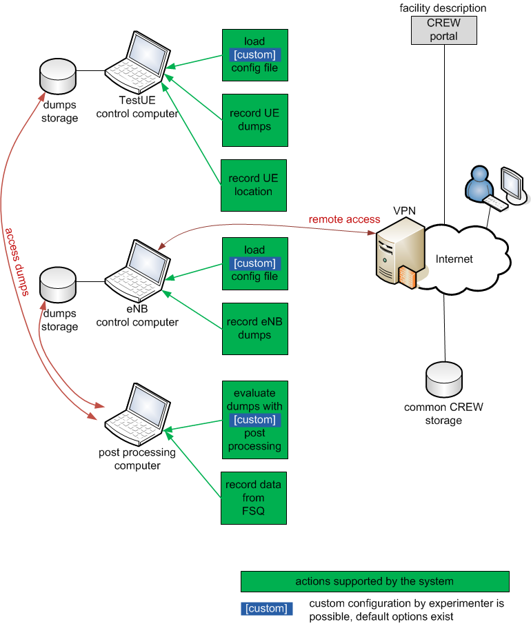
Please click on the thumbnail below to get an overview picture of the usage overview in LTE advanced testbed.
Deviations from LTE release 8
As the eNB and UE provide only minimal LTE release 8 (Rel 8) PHY/MAC functionality, it is particularly important to note that the DL frame structure and control channels differ slightly. Differences include:
- PDCCH is always in the second OFDM-symbol (position is variable according to Rel. 8),
- PHICH (HARQ Indicator Channel) is not in the first OFDM symbol and has a different structure/content,
- PCFICH (Control Format Indicator Channel) is not supported, and
- PBCH (Broadcast Channel) is not supported.
Further, the OFDM scheme is used in the uplink. Also, 5 MHz and 10 MHz mode are not supported, thus the testbed operates in 20 MHz mode only.
An overview of the uplink and downlink processing chains can be seen below:
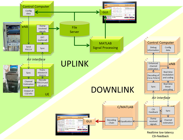
Uplink and Downlink Processing Chain
| Attachment | Size |
|---|---|
| ltep04.png | 164.57 KB |