Getting started with the experiments
If you are new to our testbed, first go through the instructions and see what needs to be done before, during and after the experiment. To get more familiar with the testbed, we recommend you to go through the basic tutorial. After you have understood that, you might want get to know the full possibilities of the testbed, and you can proceed to advanced tutorial.
Instructions for external participants
Before the experiment:
- Contact the testbed staff, make sure the hardware is compatible (frequencies) and the testbed supports all features necessary for the intended experiment
- If necessary for the experiment and after the inital contact with the research staff: Get an account to access the network and computers. Remote desktop access over internet is also possible.
- Make sure there will be enough testbed hardware available (indoor/outdoor?)
- If reasonable, ask for reference signal files to check compatibility with external hardware
- Get familiar using the spectrum analyzer R&S FSQ
- Prepare UE/eNB configuration files or ask testbed staff to do it
During the experiment:
- Carefully check the setup
- Use a terminator when there is no antenna/cable plugged
- Check if all cables are ok
- Make sure you are using the latest version of the config tool to configure the hardware
- Keep a record of the config files you use as you are changing parameters
- Check the signal on the spectrum analyzer, several things can be validated that way
- If in nothing else seems to work reboot and reconfigure the UE/eNB prototype hardware
- When in doubt, ask the testbed staff
After the experiment:
- Put everything back where you took it from
Example experiment
Detection of occupied frequency bands is the foundation for applications of dynamic spectrum access (DSA). In order to convince network operators that DSA is feasible in cellular frequencies, it has to be shown that a reliable detection of their primary signals is possible. In this section, we present an experimental validation of an algorithm and hardware, which can detect the presence of a Long Term Evolution (LTE) signal. In contrast to the classical mono antenna approach, an array of antennas is used, which allows to enhance the detection capabilities, particularly when besides the useful signal there is also interference.
Objectives of experiments
- Reliable sensing in real environment
- Performance gain of multi-antenna vs mono-antenna
- Effectiveness of primary and secondary synchonisation criteria
- Parametrization of sensing algorithm (detection threshhold)
Setup
The multi-antenna LTE sensing platform allows to acquire LTE (I, Q) data and to process them using advanced antenna processing algorithms. As described in the pictures below, the multi-antenna demonstrator is made of:
- A set of 5 antennas,
- A 4-channel receiver,
- A 4-channel acquisition board,
- A GPS system for positioning,
- A laptop for data storage and off-line multi-antenna signal processing.
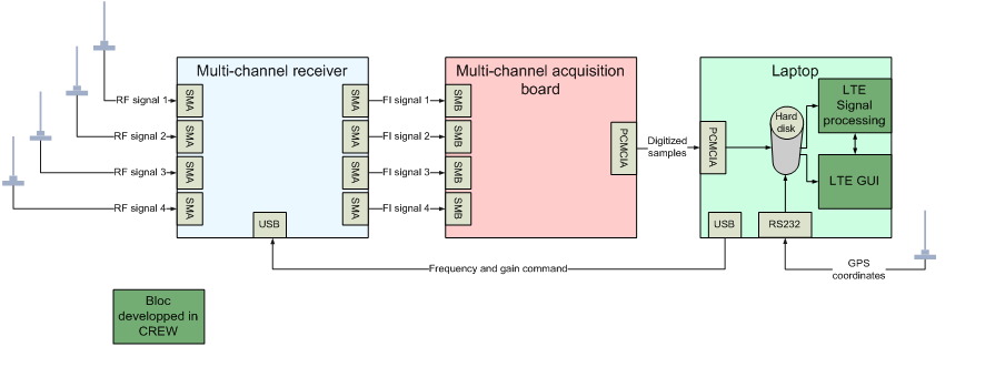
Multi-antenna sensing platform block diagram
Filtering and gain control are applied to the signal in the multi-channel receiver unit, the multichannel acquisition board is used to convert the signals to digital domain and a control computer handles processing and evaluation of the digital samples. The multi-antenna LTE sensing platform is validated with lab tests by measuring sensitivity and co-channel interference rejection with real LTE eNBs. A hardware array simulator consisting of splitters, coupling modules and a set of cables of particular lengths is employed to virtually create a multiantenna, mono-path propagation channel with two directions of arrival.
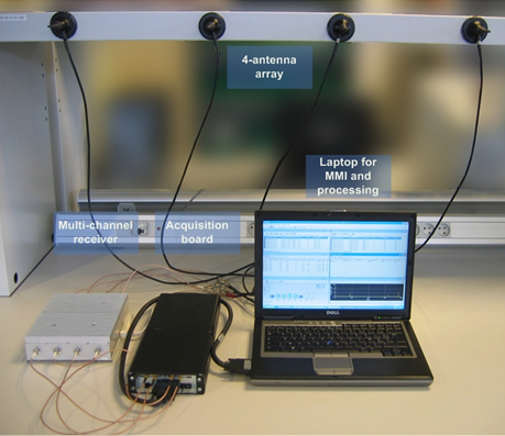
Multi-antenna sensing platform
The main characteristics of the multi-channel receiver are: frequency bands - 1920-1980 MHz / 2110-2170 MHz); bandwidth - 5 MHz; Output intermediate frequency - 19.2 MHz; Noise factor (at maximal gain) <7 dB; Rx gain - 0 to 30dB (1 dB step); Frequency step - 200 kHz; number of Rx channels – 4; Gain dispersion<1 dB; Phase dispersion<6°; Frequency stability <10-7; Selectivity at ±5 MHz >50dB.
The main characteristics of the multi-channel acquisition are: Resolution - 12 bit; internal quartz clock - 15.36 MHz; Number of channels - 4; -3 dB bandwidth >25 MHz; Memory - 8MSamples (i.e. 2MSamples per channel).
Sensitivity tests
For sensitivity measurements, the platform depicted below is used. The level of the BTS is gradually lowered in order to estimate the sensitivity level when using one or four channels for detection processing.
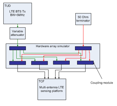
Lab test platform for sensitivity measurements
Interference rejection tests
For interference rejection measurements, the platform described in the picture below is used. The second BTS is considered as the interfering BTS in the following. Its bandwidth was set to 20MHz in order to be able to highly load the OFDM sent symbols. The level of the first BTS is gradually lowered while the level of the second one does not change. The 80% detection limit level is searched when using one or four channels for detection processing.
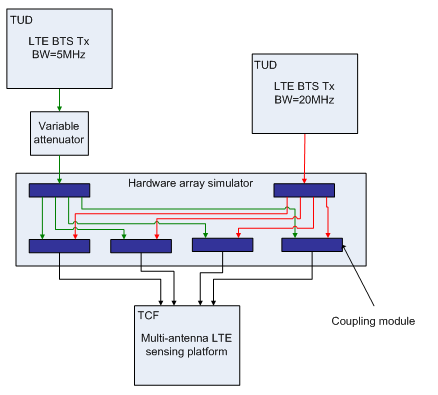
Lab test platform for interference rejection measurements
Results
LTE detection sensitivity level for an 80% detection rate
|
|
1 antenna |
4 antennas |
Multi-antenna gain |
|
Sensitivity level |
-121 dBm |
-129 dBm |
8 dB |
The LTE detection sensitivity performance is summarized in the table above. It is slightly higher to what can be expected (6 dB with 4 antennas). This might be due to a lower sensitivity of the first channel compared to the other three.
LTE rejection capacity for an 80% detection rate
|
|
1 antenna |
4 antennas |
Multi-antenna gain |
|
Sensitivity level of the first BTS |
-92 dBm |
-124 dBm |
32 dB |
|
Rejection capacity of the second BTS |
11 dB |
43 dB |
32 dB |
We can see that, with four antennas, the rejection gain is equal to 32 dB.
For further details refer to: Nicola Michailow, David Depierre and Gerhard Fettweis: “Multi-Antenna Detection for Dynamic Spectrum Access: A Proof of Concept”, QoSMOS Workshop at IEICE 2012
https://mns.ifn.et.tu-dresden.de/Lists/nPublications/Attachments/895/main.pdf
| Attachment | Size |
|---|---|
| ltep12.png | 33.27 KB |
| ltep13.png | 253.64 KB |
| ltep14.png | 14.14 KB |
| ltep15.png | 16.03 KB |
Basic tutorial
This tutorial explains how to set up a basic transmission.
Download this Zip archive with all necessary default configuration files.
Setup the eNB
- Power the hardware
- Sorbas eNB Simulator
- Radio Unit
- eNB control computer
- Configure the eNB
- Open the SimpleProxy 1.3.1 tool
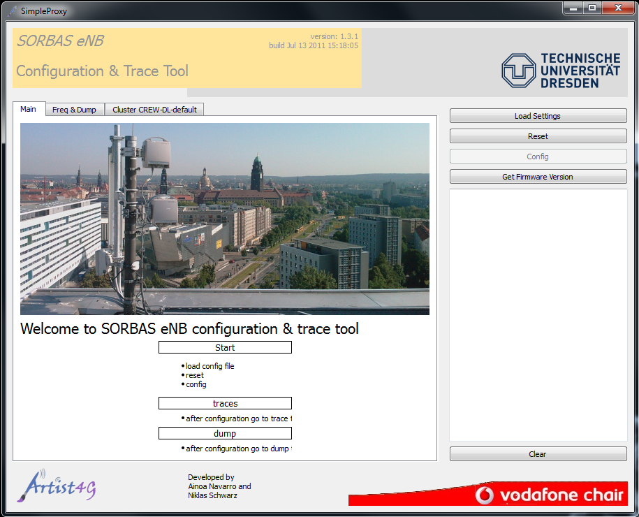
- Click Load Settings and select CREW_DL_config_default_1eNB_2UEs.xml or CREW_UL_config_default_1eNB_2UEs.xml
- Click Reset to reset the eNB
- Wait for eNB broadcast message to appear in the logging box below
- Click Config to send the configuration to the eNB
- Check logging box for errors
- Open the SimpleProxy 1.3.1 tool
Setup the UE
- Power the hardware
- Sorbas Test UE
- Radio Unit
- UE control computer
- Configure the UE
- Open the TestUE Config tool
- Select the System Config tab
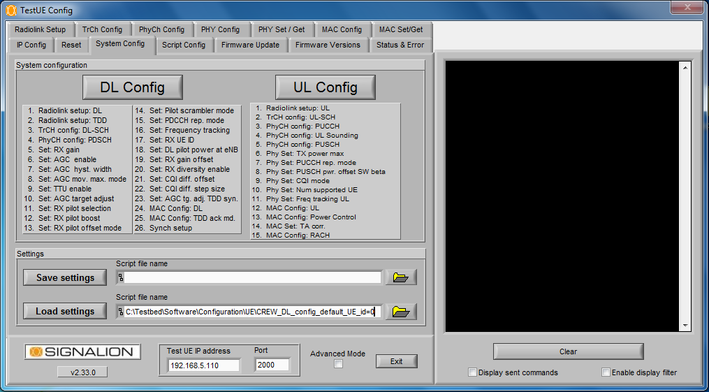
- Click Load settings and select CREW_DL_config_default_UE_id=0 or CREW_UL_config_default_UE_id=0
- Click DL config and wait for UE response
- Click UL config and wait for UE response
- Trace
- Open the TestUE Trace tool
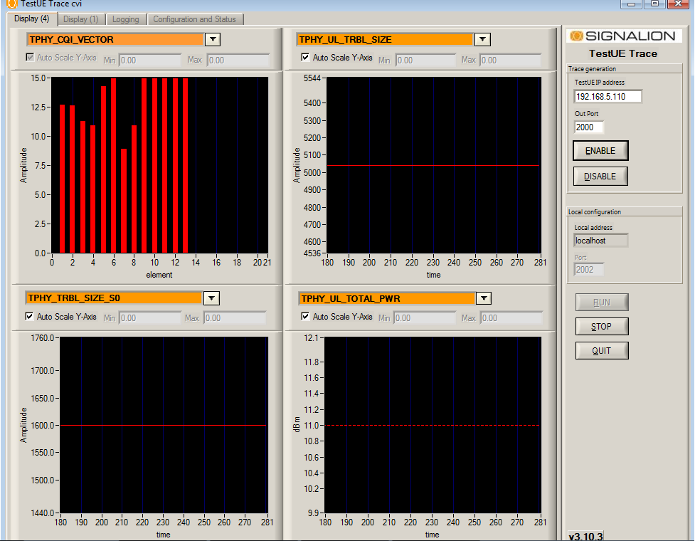
- Select the Display (4) tab
- Click Enable
- Click Run
- Open the TestUE Trace tool
The system is now running. Check spectrum on R&S FSQ. 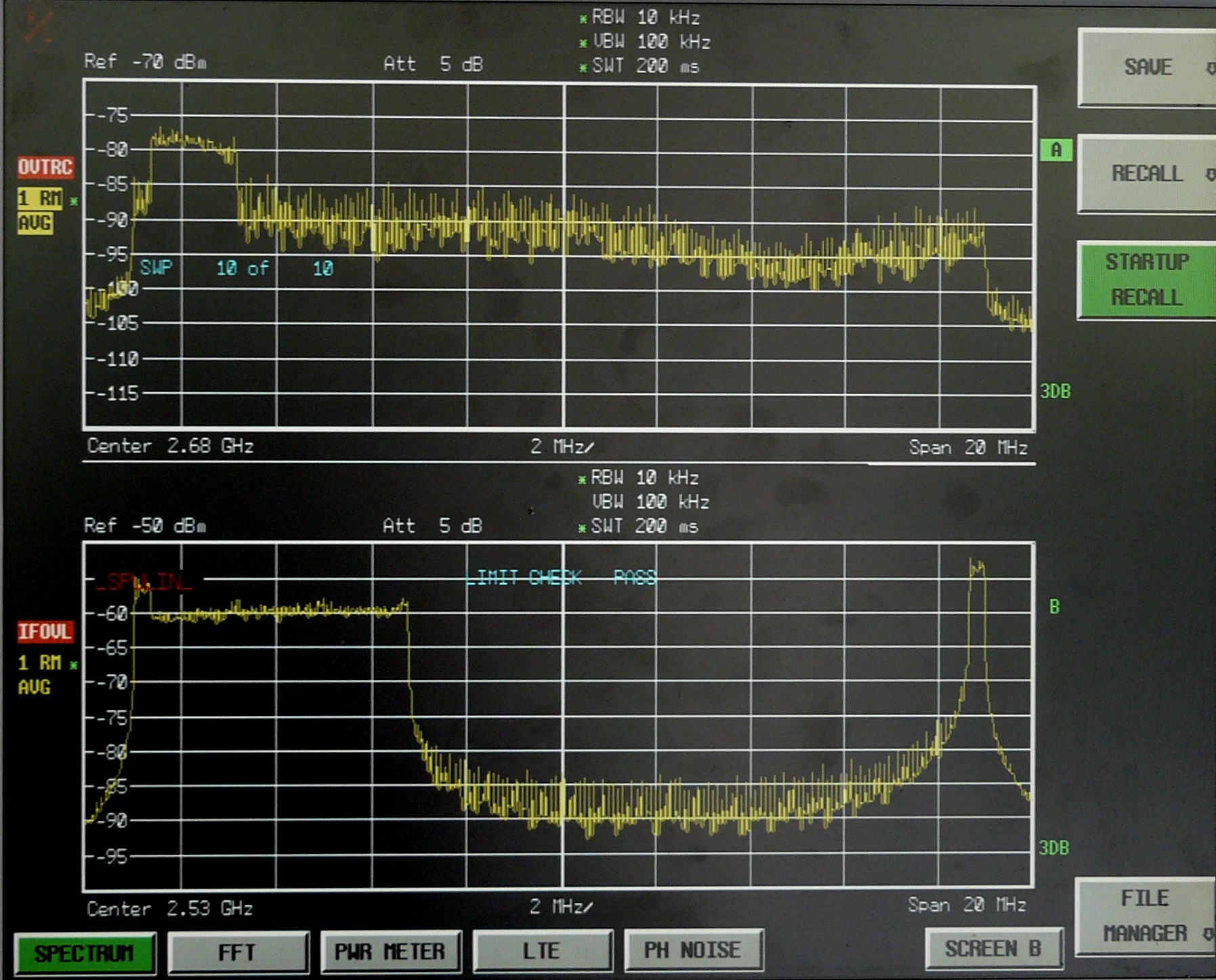
Record IQ data dumps
- Dump at the eNB
- Open the SimpleProxy 1.3.1 tool
- Click Freq && Dump tab
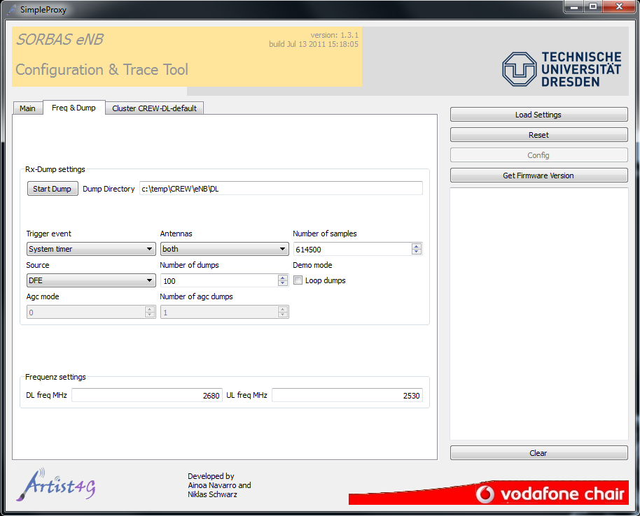
- Click Start Dump
- Dump at the UE
- Browse into the directory of the UE_dump_tool
- Click start.bat
- Process IQ dumps
- Extract IQ samples and AGC values with dumpDemux.m script
- Perform further processing in Matlab
Advanced tutorial
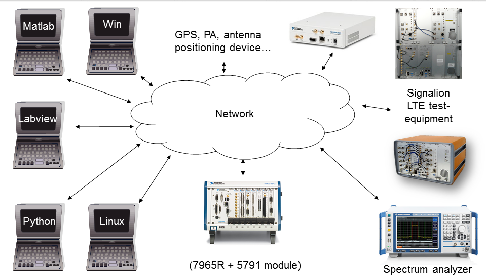
Besides the manual, gui-based control for test bed related programs and devices, script controlled measurements are also possible. This approach developed at the Vodafone chair is called TestMan. The basic idea is to provide a common interface to exchange data, commands and status messages between different application, running on the same or distributed systems and written in different languages.
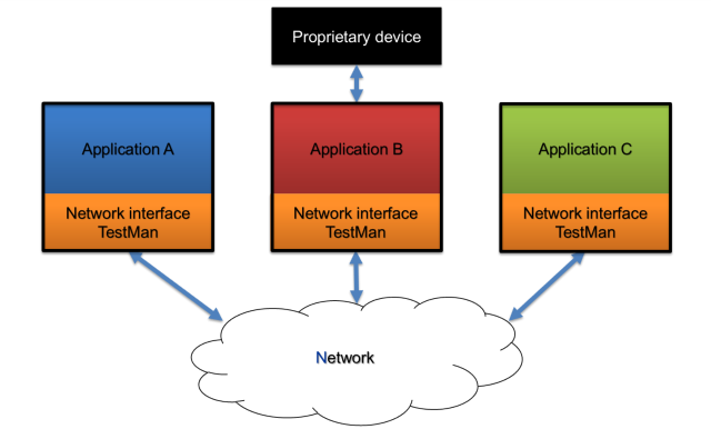
TestMan is based on the Microsofts .NET framework, which similar to java, is platform independent. So even a Linux computer can make use of .NET programs if the Mono project is used. In three important languages Matlab, Labview and Python it is possible to use dynamic link libraries (DLL). Therefore TestMan is a DLL which can be loaded into the specific application or script and it makes sure that data is transferred over the network from one Application to another, respectively to a group of applications.
TestMan uses two different network techniques to exchange information’s: For SNMP like status messages and commands UDP multicast is used whereas TCP peer to peer connection comes into place for transferring bigger data.
To distinguish between different applications a type and an ID are introduced for every application. So it is possible to group similar applications together and the TestMan DLL filters out messages which are intended for other applications.
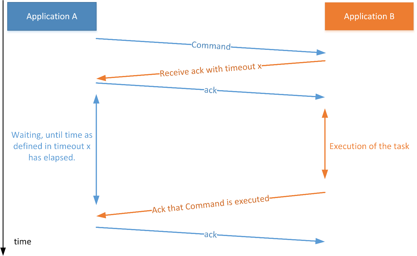
UDP packets can be thrown away by network elements like routers and switches. For a status messages this is not always a problem, but definitely when a command is send. To mitigate this problem TestMan uses 4-way handshaking for commands as stated in the following figure.
The following picture shows an example how an OFDM-Transmitter can be implemented using TestMan.
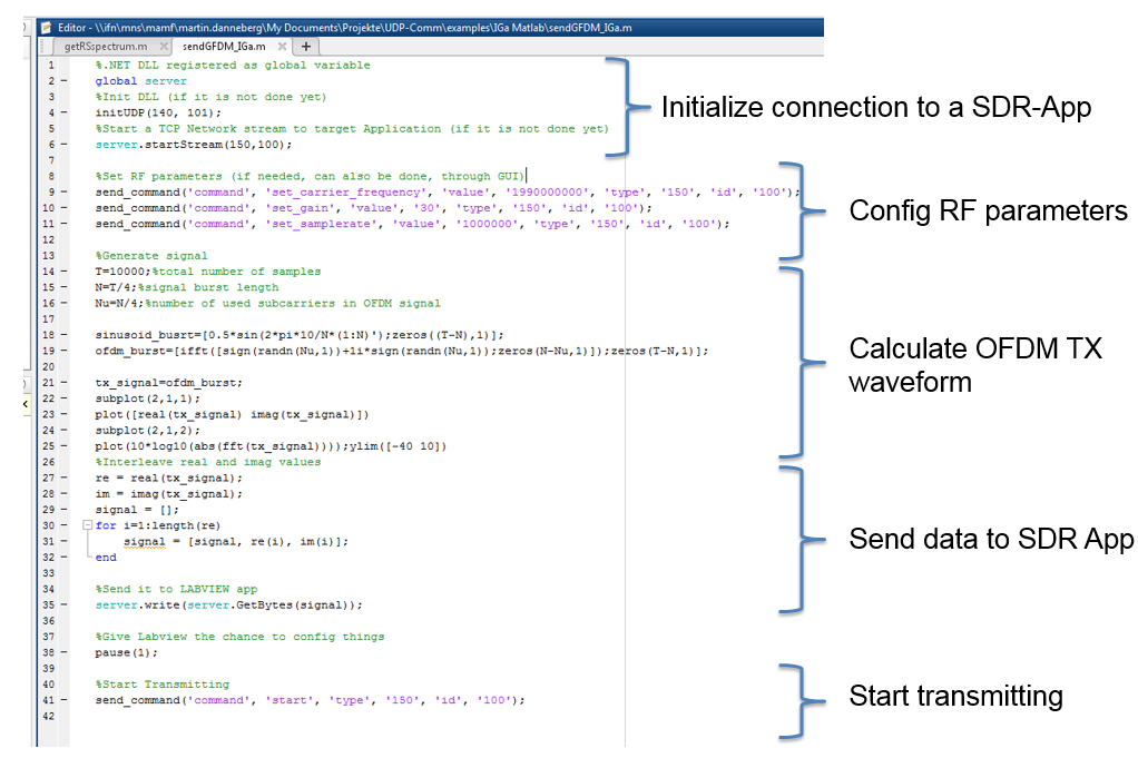
Are more detailed example code will be published soon.
| Attachment | Size |
|---|---|
| TestMan_Commands.png | 83.12 KB |
| matlab-example.png | 180.36 KB |
| TestMan_Devices.png | 243.01 KB |
| TestMan_Overview.png | 41.9 KB |