IRIS documentation
The reconfigurable radio consists of a general-purpose processor software radio engine, known as IRIS (Implementing Radio in Software) and a minimal hardware frontend. IRIS can be used to create software radios that are reconfigurable in real-time.
Please use the links below to learn more about how Iris can be used.
Testbed Description
Iris is a software radio architecture that has been developed by CTVR, The Telecommunications Research Centre at TCD, Written in C++, Iris is used for constructing complex radio structures and highly reconfigurable radio networks. Its primary research application is to enable a wide range of dynamic spectrum access and cognitive radio experiments. It is a GPP-based radio architecture and uses XML documents to describe the radio structure. This testbed provides a highly flexible architecture for real-time radio reconfigurability based on intelligent observations the radio makes about its surroundings.
Each radio is constructed from fundamental building blocks called components. Each component makes up a single process or calculation that is to be carried out by the radio. For instance, a component might perform the modulation on the signal or scale the signal by a certain amount. Each component supports one or more data types and passes datasets to other components, along with some metadata such as a time stamp and sample rate. There is a data buffer between each component to ensure the data is safe, even if one component is processing data much faster than another.
All components within the radio exist inside an engine. An engine is the environment in which one or more component operates. Each engine defines its own data-flow and reconfiguration mechanisms and runs one or more of its own threads. As with components, each engine is linked by a data buffer. Iris currently features two data types, the PN Engine and the Stack Engine. The PN engine is typically used for PHY layer implementations and is designed for maximum flexibility. It has a unidirectional data flow and runs one thread per engine. The Stack Engine is designed for the implementation of the network stack architecture, where each component is a layer within the stack and runs its own thread of execution. It also has a bidirectional data flow.
Iris’s capability to reconfigure the radio on the fly lies in the controllers. A controller exists independently of any engine and runs in its own thread of execution. A controller subscribes to events within components and reconfigures parameters in other components based on the observation of these events. For instance, a controller could be set up to observe the number of packets passing through a certain component and, upon reaching a certain number of packets, change the operating frequency of the radio.
The Iris 2.0 architecture is illustrated in the following figure.
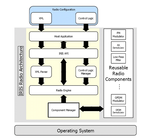
A radio is constructed and configured using XML documents. Each component is named and has its inputs, outputs and exposed parameters explicitly specified. Engines are declared and components are placed in their relevant engines. Controllers are then declared at the top of the XML document and the links between each component are declared at the end of the document.
The layout of the testbed hardware can be found here .
The testbed can be accessed directly here .
Apply for an account
Before gaining access to the Iris testbed it is essential to familiarise yourself with the Iris software. This is done through the Iris Wiki page. The Wiki gives you full instructions on how to download and install the Iris software onto your own computer as well as instructions on how to get started in using it. Use of the Wiki page requires a user account and password. These can be obtained through emailing either tallonj@tcd.ie or finnda@tcd.ie.
An overview of the Iris architecture and some of its capabilities are available here .
At this stage users will be able to performe experiments using Iris, independent of the Iris testbed, using either the simulated "channel component" or in conjunction with the USRP (1/2/N210 etc.).
Access to the Iris testbed is given out separately from access to the Wiki. This is because access to the Iris testbed is often not necessary if users have USRP hardware of their own available.
However, if remote access to the Iris testbed (after installing and trying out the Iris software) is required, details of how to obtain access to the testbed can be found here.
Remote access
The CTVR Iris testbed is currently being reconfigured. The node locations may not reflect exactly those shown in the diagram. For downtimes make sure to check the calendar.
The testbed is designed to permit fully remote access for carrying out experiments. This page provides information required to use the testbed from a remote location.
Access to the Iris testbed is achieved through the ctvr-gateway server. User login details are required to gain access to this server. These can be applied for by emailing either tallonj@tcd.ie or finnda@tcd.ie explaining the nature of the experimentation desired to be carried out within the testbed. Due to limitations in the number of nodes available applications must be handled on a case by case basis.
Once login details have been obtained
The experimenter will need to schedule an experiment.
Remote VNC Access
The experimenter will then be able to access any of the testbed nodes via VNC in the following way. Use the login details you were issued to login to ctvr-gateway.cs.tcd.ie via SSH. Once you have a terminal for this server open, SSH again onto the node you wish to access as follows:
ssh nodeuser@ctvr-node07.cs.tcd.ie
vncserver :1 -geometry 1280x900
This will create a vncserver on display 1 of node 07 and with a 1280x900 screen resolution. Once the server is running, use a VNC client to connect. In this case, we would connect to ctvr-node07.cs.tcd.ie:1. When you are finished, kill the VNC server on the testbed node as follows:
vncserver -kill :1
The following pages will be of use in setting up an experiment:
| Iris architecture overview | Iris Testbed Layout | Powering the USRPs remotely |
|---|---|---|
|
 |
 |
| Spectrum analyser remote access | First example experiment | Use fo the testbed webcam |
 |
 |
 |
Use of licensed bands
For use of wireless spectrum outside of unlicensed bands the experimenter is directed here.
| Attachment | Size |
|---|---|
| Iris Experiment.jpg | 79.47 KB |
| webcam_symbol.png | 6.43 KB |
First example experiment
The full installation instructions for iris can be found at:
https://ntrg020.cs.tcd.ie/irisv2/wiki/ExampleExperiments
The wiki contains information on how to install iris on both Windows and Linux OS.
As well as information on how to run a radio and on the test bed in general.
In this sample experiment we will run a simple radio and then adapt a component and add a controller, with a view to exploring the basic functionality of both. The steps a researcher should follow to complete the experiment are outlined below.
1. Follow the instructions outlined in the wiki to run radio, OFDMFileReadWrite.XML
2. If this radio is functioning correctly, “radio running” will appear on the command line.
3. To add a controller to the radio, we must first create an event in one of the components to which the controller can subscribe. To do this, open the shaped OFDM modulator and register an event in the constructor function.
4. Once the event is registered we must create a condition that must be satisfied for the event to be activated. To do this, open the “process” function (as this is where all the calculations are carried out) and specify a condition that activates the controller whenever, for example, 100 packets have passed through.
5. Once this has been done the controller can be made. Open the “example” controller; this gives us a template to work with.
6. Within the controller we must do two things, subscribe to the event that has been set up in the component and specify the parameter that we wish to change as well as the value we wish to change it to.
7. To change the parameter, we specify the name of the parameter as well as the component and engine that it is in. These are assigned in the “ProcessEvent” function.
8. The logic that dictates what the parameter is changed to also goes in this function.
9. Recompile all the relevant code, include the controller in the XML file and run the radio as before.
If the radio is running properly, you should see the event being triggered on the command line and the new value of the parameter in question.
Control of the USRP remote power switches
Powering the USRPs
In the testbed we have installed two remote power switches which allow us to remotely power each of the USRPs on and off. To access the remote power switches you must first be logged into one of the testbed nodes. Details on obtaining access can be found here. These switches can be controlled through web interface.
Access the switches by navigating to
or
http://ctvr-switch02.cs.tcd.ie
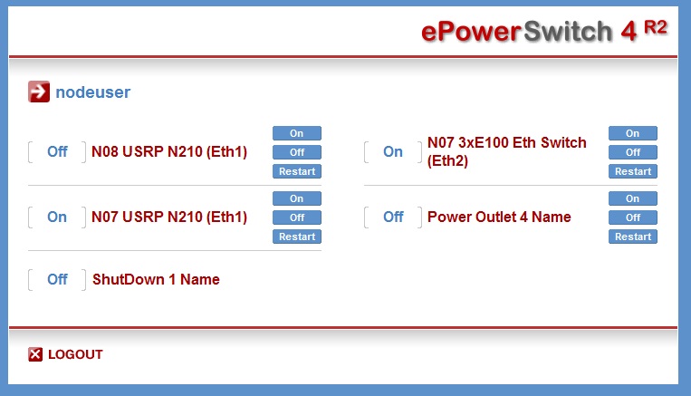
in the web browser of one of the testbed nodes (again, the power switch interfaces can only be accessed from the testbed nodes). On doing so you will see a similar interface to the following:
The login details are identical to those used to access the nodes themselves. Here, you can power the USRPs for each node on and off. Please remember to power USRPs off when you have finished using them. The positioning of the different testbed nodes as well as the spectrum analyser and signal generator can be found here .
Powering the USRPs via command line/scripts
The remote switch can also be accessed via HTTP Post commands, using a tool such as curl, or equivalent calls in a script or program. Using a UNIX based system with curl installed
curl --data 'P<port>=<command>' http://nodeuser:ctvrnodepass@ctvr-switch.cs.tcd.ie/cmd.html
will alter the state of socket <port> according to <command>.
<port> choices are as follows:
For switch http://ctvr-switch.cs.tcd.ie
* 1 - Node 08 USRP N210 (ETH1)
* 2 - Node 08 USRP N210 (ETH1)
* 3 - Node 05 USRP N210 (ETH1)
* 4 - Node 06 USRP2 (ETH1)
For switch http://ctvr-switch02.cs.tcd.ie
* 1 - Currently unspecified
* 2 - Currently unspecified
* 3 - Currently unspecified
* 4 - Currently unspecified
<command> choices are:
* 0 - Switch Off
* 1 - Switch On
* t - Toggle state
* r - Restart
Commands to multiple ports can be strung together using ampersands, as per the following example:
curl --data 'P0=r&P1=r&P2=r' http://nodeuser:ctvrnodepass@ctvr-switch.cs.tcd.ie/cmd.html
| Attachment | Size |
|---|---|
| e-power switch.jpg | 63.91 KB |
Iris Testbed Layout
The CTVR Iris testbed is currently being reconfigured. The node locations may not reflect exactly those shown in the diagram. For downtimes make sure to check the calendar.
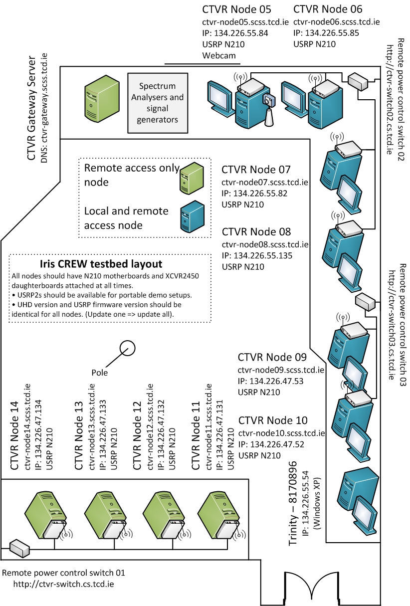
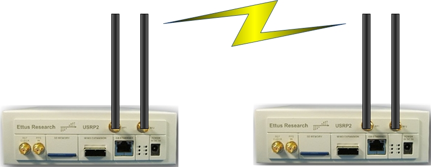
The testbed is laid out as follows. Currently there are 8 remotely accessible Quad core machines each equipped with a USRP2/N210 and an XCVR2450 daughterboard. The USRP2s have a 24 MHz bandwidth (using Gigabit Ethernet to communicate between the USRP and the computer). The daughterboards are capable of transmitting between 2.4 and 2.5 GHz and also between 4.9 and 5.9 GHz.
The testbed diagram shows the "fixed" testbed layout; however, a some "custom" layouts may also be accommodated for specific experiments.
Additionally, before running an experiment on the testbed, experimenters must gain login details for the ctvr-gateway node, through which all of the other testbed nodes are accessed. Information on applying for login details can be found here. Experiments must also previously be scheduled on the testbed calendar, details of which can be found here.
| Attachment | Size |
|---|---|
| Testbed_Diagram_v5.2.jpg | 485.72 KB |
Iris Testbed best practices
1. Everything in the testbed has an exact place
· Each USRP and node has been assigned a table and number.
· Unused daughterboards will be placed in proper storage places.
2. Everything goes back to the exact place after any experiment that causes it to be moved.
3. Clonezilla is used on all nodes meaning that nodes will be reset to a specific version of IRIS on startup.
4. Bearing this in mind everyone should take care to store data in the data partition and not elsewhere on a node as it will be lost otherwise.
5. The firmware in the USRPs will be updated when a new release becomes stable. All hardware will be updated at once rather than a subsection of hardware.
6. If it is found that any piece of equipment gets broken, or if there is an issue with its functionality (e.g. only works for a certain bandwidth or really low powered) the IRIS testbed users mailing list iris-testbed-users@scss.tcd.ie must be informed. This will be relayed this to the wider group and a note will be made of this on the appropriate wiki pages https://ntrg020.cs.tcd.ie/irisv2/wiki/TestbedInventory.
7. All experiments must be scheduled using the Google calendar <ctvr.testbed> specifying all of the following:
· Name of experimenter
· Date and time of booking
· Testbed node number(s)
· Daughtboard(s) of use
· Frequency range(s) of use
8. The testbed should not be used for simulations.
9. The testbed room should be kept secure.
10. Testbed users should sign up to the following mailing lists:
· IRIS support mailing list https://lists.scss.tcd.ie/mailman/listinfo/iris2
· IRIS testbed users mailing list https://lists.scss.tcd.ie/mailman/listinfo/iris-testbed-users for enquiries regarding the Iris testbed.
· IRIS commit mailing list https://lists.scss.tcd.ie/mailman/listinfo/iris2commit for commit notifications.
11. Short descriptions of all experimental work using the testbed should be provided in the projects section of the IRIS wiki https://ntrg020.cs.tcd.ie/irisv2/wiki/ActProjects.
Scheduling an experiment
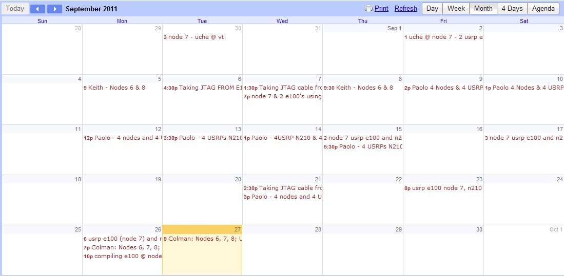
On receiving testbed login details, the experimenter will also be issued with access to the Google calendar used for scheduling experiments. It is essential to schedule experiments, specifying:
* Which nodes
* Number of USRPs/daughterboards
* Frequencies of operation
* If the spectrum analyser/signal generator is also needed
* Your name
prior to use of the testbed.
An example shot of the calendar is shown below.

| Attachment | Size |
|---|---|
| ctvr_testbed_google_calendar.jpg | 101.79 KB |
Spectrum analyser remote access
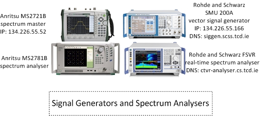
The main spectrum analyser in the testbed room is a Rohde & Schwarz FSVR real-time analyser.
- Host name: ctvr-analyser.cs.tcd.ie
- IP address: 134.226.55.156
- Frequency range: 10Hz - 7GHz
- Frequency range: 10Hz - 7GHz
- Support for IQ analysis (inc. OFDM)
- Maximum sampling rate for IQ acquisition: 128MS/sec
The spectrum analysers are situated as shown in the testbed layout diagram; however, we can easily relocate the receive antenna of the spectrum analyser around the lab if needs be for a certain experiment. We also have in the testbed:
- Rohde & Schwarz SMU 200A - Vector Signal Generator
- Anritsu MS2781B - Signal Analyser
- Anritsu MS2721B - Spectrum Master (handheld spectrum analyser)
Probably the easiest way to acquire data from the Rohde & Schwarz spectrum analyser is using the testbed Windows node "Trinity-8170896" which is accessible via VNC through the ctvr-gateway node. This node runs Rohde & Schwarz IQWizard, a programme which allows simple acquisition of IQ data, in a range of formats. However, remote access directly to the spectrum analyser via VNC is also available.
Remote access via VNC
The spectrum analyser can be accessed from any of the testbed nodes or from the ctvr-gateway server. Information on obtaining access to these nodes can be found here.
* Verify that the analyser is switched on and connected to the network by pinging it using
ping ctvr-analyser.cs.tcd.ie
* Use a VNC client to connect to ctvr-analyser.cs.tcd.ie
Remote control and IQ acquisition using Matlab
It is also possible to perform remote control and IQ acquisition using Matlab.
| Attachment | Size |
|---|---|
| Generators and Analysers - one SigGen.jpg | 87.51 KB |
Test and Trial Ireland
In order to enable research into innovative new technologies, which would require transmission and reception testing within licensed bands, Test and Trial Ireland have the ability to make certain bands in the Irish wireless spectrum available for use. Test and Trial Ireland is a licensing programme which was launched by the Commission for Communications Regulation in Ireland (ComReg).
If the experimenter requires use of licensed bands further details on the programme, as well as information about how to apply for spectrum, are available at http://www.testandtrial.ie/.
![]()
Use of the testbed webcam
In order to view the testbed remotely and to enable experiments with live camera streaming a webcam has been added to the testbed on node05.
The easiest way to veiw the testbed using the webcam is by connecting to node05 via VNC and opening "Cheese Webcam Booth".
We can also reposition the camera if required for certain experiments.