CREW offers Open Access

CREW is in continuous Open Access phase to support your experiments free of charge!

Final public event & Globecom tutorial

CREW will present its final results at the Wireless Community event (Leuven, Belgium, 29 October 2015, more info) and organises a hands-on tutorial at Globecom (San Diego, USA, 10 December 2015, more info)

CREW PORTAL: access the CREW facilities

Interested in using the CREW facilities?
[Start here] - [Browse by name] - [Overview images] - [Advanced info] - [WTA GitHub].

Program examples using the Imec sensing engine API

The Imec sensing engine is programmed in C, and can be set-up, configured and used with the sensing API. Using a simple example the use of this API is illustrated for the FFT_SWEEP mode. Both a single FFT sweep as multiple FFT sweeps are shown. This is illustrated for an Imec sensing engine equiped with a WARP front-end. A zip archive containing the source code of the examples is included below.

To conclude we provide an overview of the other modes as supported by the Imec sensing engine.

FFT_SWEEP example

The Imec sensing engine supports several modes: for this example uses FFT_SWEEP sensing scheme. This returns 128 points per selected channel. Figure 1 shows the output of one FFT sweep, for channel one to four for WARP, covering center frequencies 2412, 2432, 2452, 2472.

single FFT sweep result

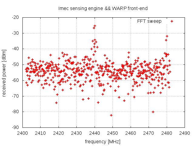
Figure 1 Output of one FFT sweep in the ISM band


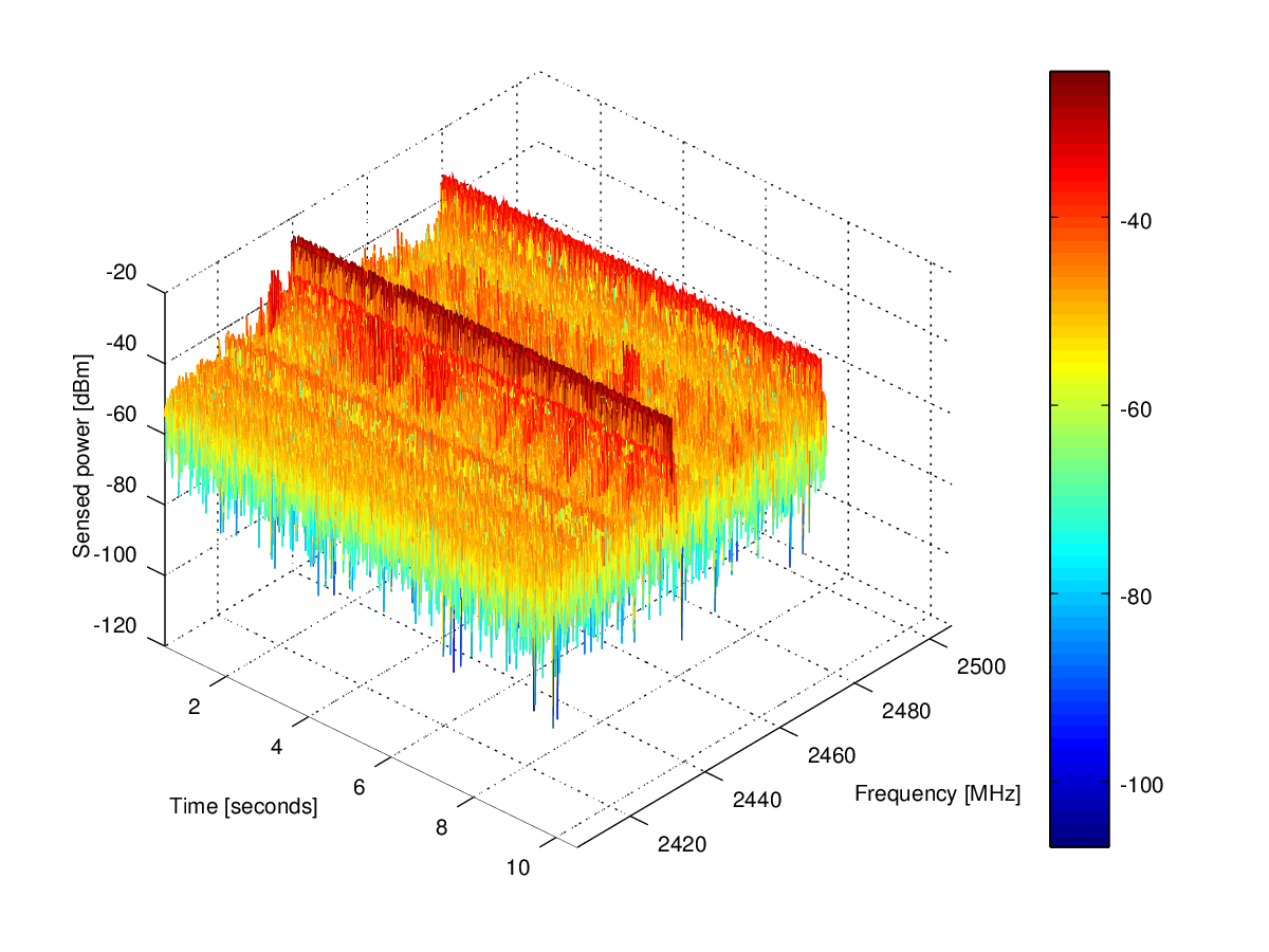
The sensing engine is programmed in C. Items (1) .. (8) show the necessary steps to configure the sensing engine, and to produce the data shown in Figure 1. The full source code is available in the zip archive, specifically in the warp_single_FFT_SWEEP.c program file. In (9) we show how the program can be extended to do multiple sweeps.

The next paragraph discuss the required calls to the sensing API to produce the result.

Convention:

Type declarations are highlighted in green, and code snippets in blue. Calls to the sensing engine API are underlined.

1) Open the sensing engine handler 

   To open an Imec sensing engine board both the spider number and

    front end number need to be used. The output is a software handler 

    that is used for the sensing engine API function calls.


  se_t sensing_engine_handler;

  sensing_engine_handler = se_open(spider, warp); 

  With:

  • spider: an integer containing the spider board number. This number is bigger than 128 for spider v2 boards
  • warp:  a constant value 0 to select the WARP front end.


2) Initialize sensing engine

    After checking the status of the sensing engine,  the se_init function is

     invoked to allocate memory and start adres for the my_se_config struct. 

     With this struct the parameters for the sensing engine will be configured.

     A return value equal to 1 indicates that this step succeeded

    int result = 0;

    struct se_config_s my_se_config;

 
    if (se_get_status(sensing_engine_handler)) {
      result = se_init(sensing_engine_handler, &my_se_config);
    }
    assert (result==1);
 
 
3) Configure the FFT_SWEEP parameters, and check the configuration   
 
    The my_se_config senging engine paremeters are configured, 
    and validated with the se_check_config() function. A return value of 1
    indicates that the configuration successfully passed all
    checks of the input parameters for the Imec sensing engine. 
 
 
    int start_channel = 1;
    int stop_channel = 4;
 

   // configure WARP FFT sweep  

    my_se_config.first_channel = start_channel; 
    my_se_config.last_channel = stop_channel; 
    my_se_config.fe_gain = 100; // 100 = max gain
    my_se_config.se_mode = FFT_SWEEP;
    my_se_config.bandwidth = 10450000;
 
    // check configuration 
    result = se_check_config(sensing_engine_handler, my_se_config);
    assert(result == 1);
 
 
4) Load configuration to sensing engine, and allocate space for the return values
 
     The verified configuration is now written into the Imec sensing engine for real,
      and returns the number of floating point samples that are returned. 
      This allows to reserve memory space for return values, as illustrated below.
 
      The configuration can be used once, or applied continously. 
       In this example we opt for one FFT_SWEEP for the configured channels.
 
    float *fft_result;
 
    result = se_configure(sensing_engine_handler, my_se_config, 0);
    // 0 for single sweep, 1 for continuous sweeping
 
    // allocate space for output values
    fft_result = (float *) malloc(result*sizeof(float));
 
 
5) Start measurement
     
   The sensing is started as follows:
    
    se_start_measurement(sensing_engine_handler);
   
 
   This procedure is the same for single and continuous sweeping.
   Note however that for the continuous mode only one call to the
   se_start_measurement function is required.
 
 
6)  Read out result of the scan into the fft_result array
 
    The se_get_ressult() function returns the measument data.
    For this example 4 times 128 values are returned.
    A return value of 1 indicates that the FFT sweep was successful
 
   result = se_get_result(sensing_engine_handler, fft_result);
   assert(result==1);
 
   Note that this function can be called only once in this example. 
   If continous mode is selected multiple calls can be done to this functin to 
   get the most recent sensing data.
 
7)  Close the spider board
 
   In this example only one sensing sweep was needed,
   hence the sensing engine can be closed as follows:
   
   se_close(sensing_engine_handler);   
 
8) Process  results
 
  In this example the content of the fft_result array is written into a file called
   
  warp_single_fft_scan.log
 
  The result can be inspected with the gnuplot command,
  as shown here.
 
9) Extension of the example
 
An extention of the single FFT sweep for WARP is provided in the warp_multiple_FFT_SWEEP.c file. The sensing engine is configured in continuous mode, and repeated measurements are colleced, and dumped in a file called warp_multiple_fft_scan.log . The result can be visualized with the warp_meshview.m script, that can be executed in matlab or octave, as illustrated in Figure 2 below. We observe that the highest energy is observed in frequency bands around 2440 and 24480 MHz.


3D plot of multiple FFT sweeps
Figure2: Sensing output for multiple FFT sweeps.
 

Other sensing modes

Programming other sensing modes follows the same procedure as shown in the example above. Here we list the supported modes. These are detailed in appendix A of the Sensing engine user manual. Note that Scaldio2B and WARP RF front-ends sweep in other bands, hence channel numbers do not correspond. 
 
  1. FFT_SWEEP : shown in example above. A 128 point FFT is performed for each configured channel.
  2. WLAN_G: determines the instantaneous power in each selected channel for IEEE802.11g spectrum.
  3. WLAN_A: similar as WLAN_G, for IEEE802.11a spectrum.
  4. BLUETOOTH: determines instantanious power for IEEE802.15.1 spectrum. 
  5. ZIGBEE: similar to BLUETOOTH, for IEEE802.15.4 spectrum
  6. LTE: not implemented.
  7. DVB_T: detection of DVB_T signals. Only applicable for the Scaldio2B front-end.
  8. ISM_POWER_DETECT: determines instantaneous power in the 2.4 GHz ISM band, with a granularity of 1 MHz. 
  9. TRANSMIT: not implemented.
  10. ADC_LOG1: logging of ADC values as retrieved from the front-end. Debug mode for sensing engine equiped with a Scaldio2B front-end.  
  11. ADC_LOG2: logging of ADC values as retrieved from the front-end. Debug mode for sensing engine equiped with a WARP front-end.
  12. STANDBY: not implemented.
 
AttachmentSize
WARPexample.zip5.62 KB
Imec-sensing-engine-WARP-single-FFT-sweep.png10.84 KB
Imec-sensing-engine-WARP-multiple-FFT-sweep.png324.93 KB